Frame of motorcycle and engine bracket

Active Publication Date: 2006-08-03
KAWASAKI MOTORS LTD
View PDF11 Cites 30 Cited by
  • Summary
  • Abstract
  • Description
  • Claims
  • Application Information

AI Technical Summary

Benefits of technology

[0033] In an engine bracket thus configured, the region which is required to have strength sufficient to withstand the tensile stress is made thicker, and the engine bracket is able to have suitable strength. In addition, the region in the vicinity of the region that is subjected to the tensile stress is adjusted to have suitable flexibility while achieving a lightweight engine bracket. Furthermore, a strong and lightweight engine bracket may be manufactured by a forging process.
[0034] The engine bracket may include a frame side co

Problems solved by technology

The process for welding a number of components is complicated, making it difficult to improve productivity.
Since the entirety of the brackets is of a predetermined uniform thickness, weig

Method used


Image

  • Frame of motorcycle and engine bracket
  • Frame of motorcycle and engine bracket
  • Frame of motorcycle and engine bracket

Examples


Example

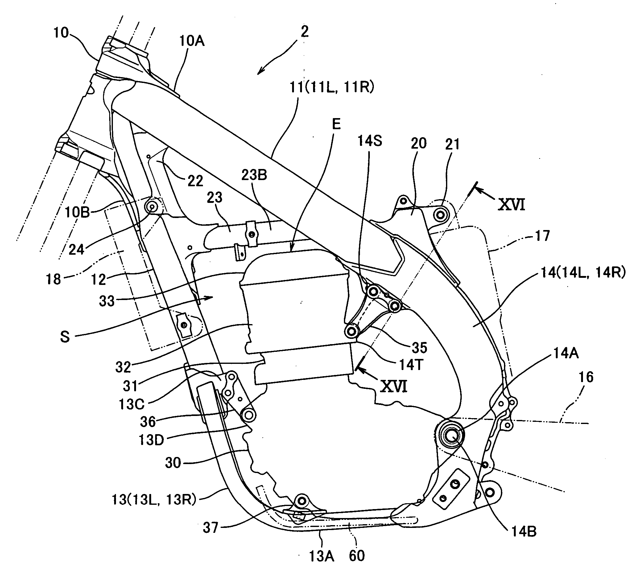
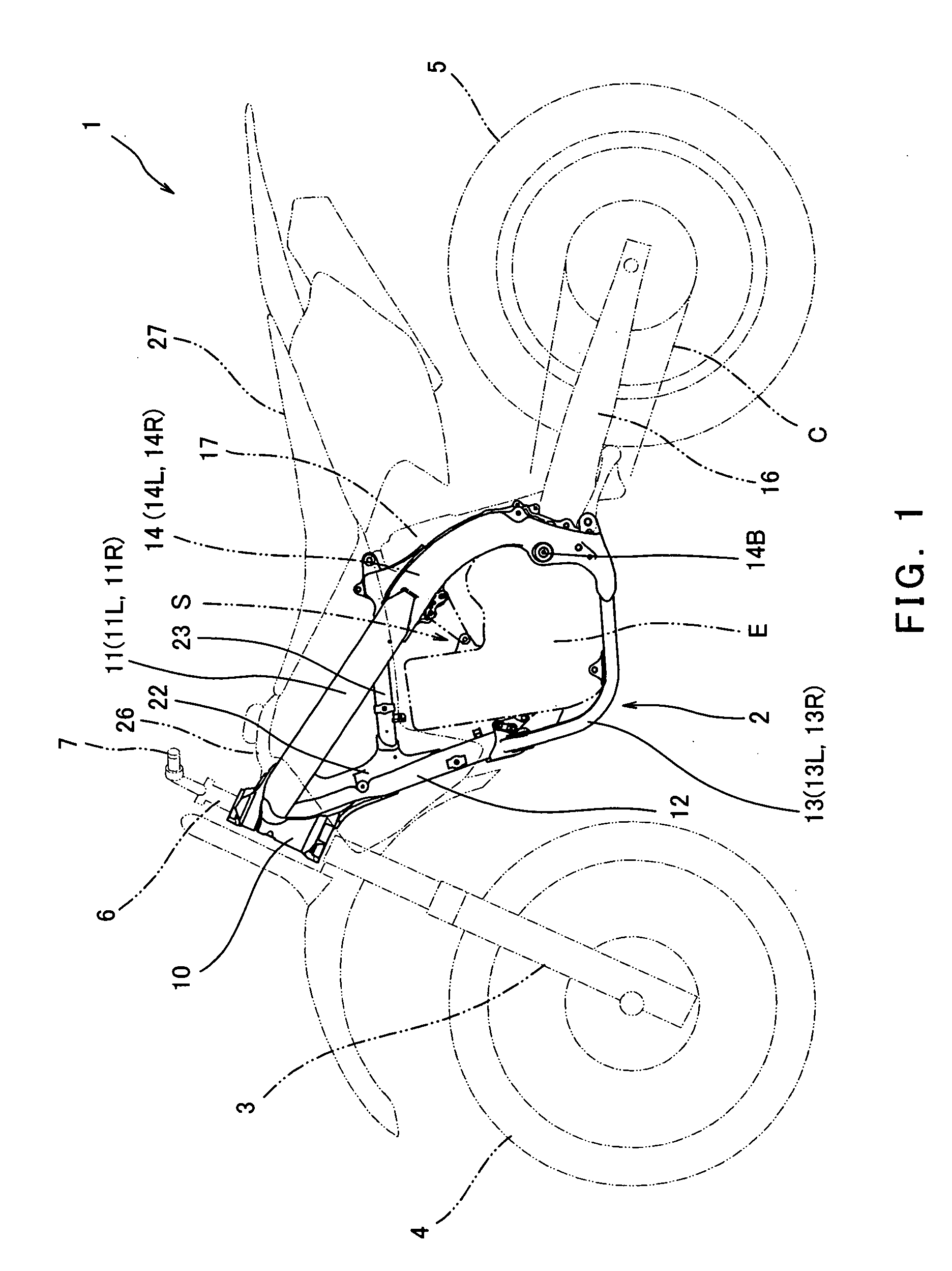
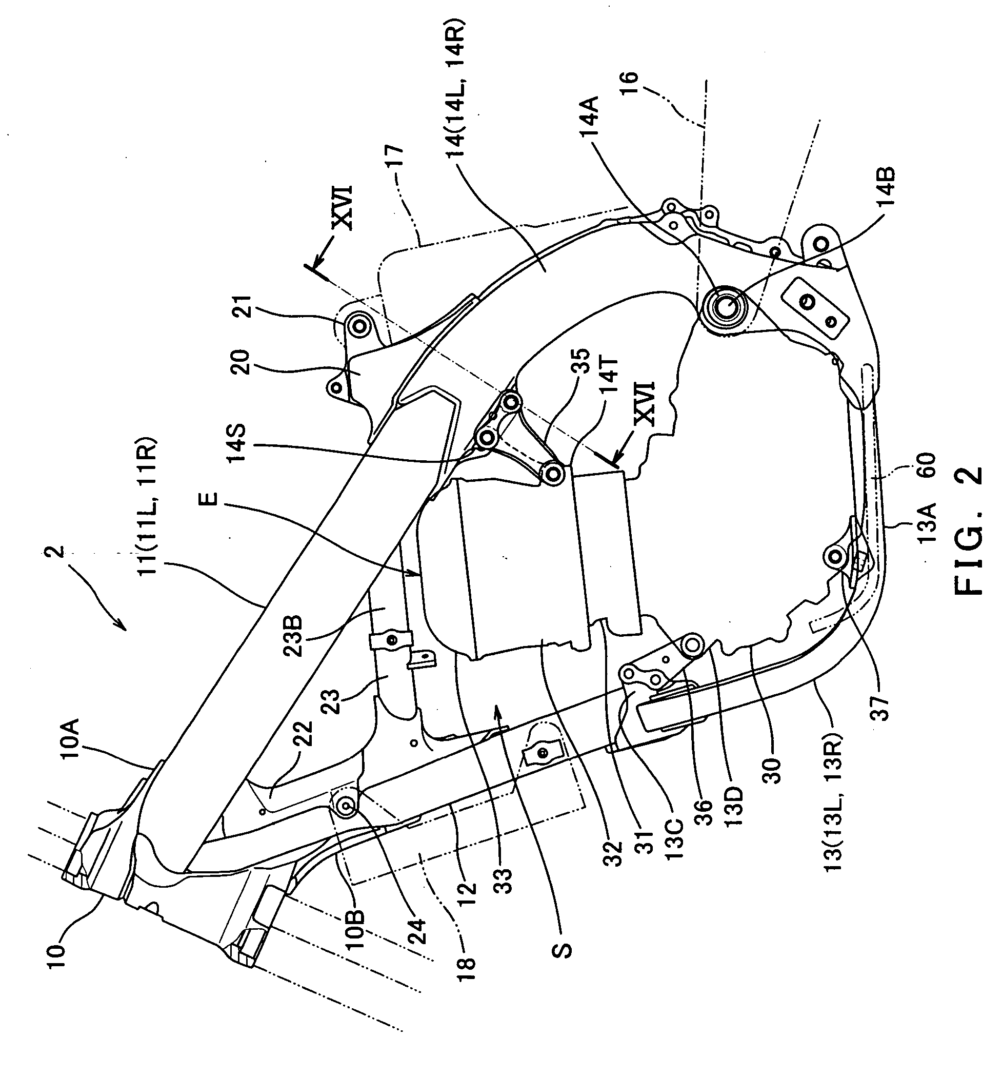
[0053] Hereinafter, a frame of a motorcycle according to an embodiment of the present invention will be described with reference to the drawings. FIG. 1 is a side view of a motocross motorcycle 1. FIG. 2 is a side view of a frame 2 of the motorcycle 1 of FIG. 1. The frame 2 of this embodiment is typically made of aluminum alloy, however it will be appreciated that the frame may alternatively be made of other suitable materials. In FIG. 1, the frame 2 is illustrated by a solid line and the other parts are illustrated by two-dotted lines. Herein, directions are defined from the perspective of a rider (not shown) straddling the motorcycle 1.

[0054] Turning now to FIG. 1, the motorcycle 1 comprises a front fork 3 extending substantially vertically with a predetermined caster angle. A front wheel 4 which is a steering wheel is rotatably mounted to a lower portion of the front fork 3. A lower portion of the steering shaft 6 extending substantially vertically is coupled to an upper portion...


PUM


Abstract

A frame of a motorcycle includes a head pipe configured to support a steering shaft, a first frame configured to extend from the head pipe, through above and rearward of an engine, and to rearward of a vehicle body, a second frame that is located under the first frame and configured to extend from the head pipe, through forward and downward of the engine, and to rearward of the vehicle body, a bracket by which a first component is mounted to the second frame, and a coupling member that is mounted to the second frame to couple a second component to the second frame, and the bracket is integral with the coupling member. An engine bracket of a motorcycle is manufactured by forging such that a region subjected to tensile stress is made thicker than a region in the vicinity of the region which is subjected to the tensile stress.

Description

TECHNICAL FIELD [0001] The present invention generally relates to a frame of a motorcycle, and an engine bracket by which an engine is mounted to the frame. BACKGROUND ART [0002] Some frames of motorcycles include a head pipe that supports a steering shaft with a steering handle attached to an upper portion thereof, a main frame extending rearward from the head pipe, a down tube extending downward from the head pipe, a lower frame extending substantially rearward from a lower end portion of the down tube, and a pivot frame (also referred to as a swing arm bracket) extending downward from a rear end portion of the main frame, by which a rear end portion of the lower frame is coupled to the rear end portion of the main frame. Such a construction is disclosed in Japanese Laid-Open Patent Application Publication Nos. 2004-331001 and 2004-330999. [0003] Various components are incorporated into the frame including the main frame, the pivot frame, the down tube, and the lower frame. One ex...

Claims


Application Information

Patent Timeline
IPC IPC(8): B62K11/00
CPCB62K11/00B62K11/04
Inventor KUROKAWA, NOBUHIKOMASUDA, YOSHIHIRONAKASHIMA, TAKEHIROTAKASU, AKIRAMIYAKE, TOSHIYUKI
Owner KAWASAKI MOTORS LTD
Why Eureka
Try Eureka