Ceramic filtration membrane

a filtration membrane and ceramic technology, applied in gravity filters, filtering materials loosening, separation processes, etc., can solve the problems of sintering temperature negatively affecting the manufacturing cost of filtration membranes, microfiltration ceramic layers having pore sizes greater than 50 nm, and high oven cost, etc., to achieve low manufacturing cost, high filtration efficiency, and high filtration efficiency

Inactive Publication Date: 2015-09-17
LIKUID NANOTEK
View PDF5 Cites 9 Cited by
  • Summary
  • Abstract
  • Description
  • Claims
  • Application Information

AI Technical Summary

Benefits of technology

[0013]The present invention proposes a ceramic filtration membrane having suitable porosity, strength, resistance and a low manufacturing cost as a result of the structural characteristics of the porous support forming it.

Problems solved by technology

The manufacturing cost depends mainly on the temperature of the sintering or densification process because the higher the sintering temperature, the higher the energy cost required for binding the particles and the higher the cost of the oven needed.
In contrast, when aluminum oxide is used, given then its atomic conductivity is less than that of zirconium dioxide or titanium dioxide, the sintering temperature negatively affects the filtration membrane manufacturing cost since high temperatures greater than 1700° C. are needed for sintering aluminum oxide particles.
A support having a suitable porosity greater than 25% is also obtained with this composition; however, by using aluminum oxide particles with a. particle size of 4 μm-12 μm, the pore size of the obtained support is relatively small and can cause problems when depositing ceramic particles with coarse particle sizes, which will give rise to microfiltration ceramic layers having pore sizes greater than 50 nm.
This would entail the need to develop several porous supports to enable covering all the ceramic membrane filtration ranges, which would limit technical-economic product feasibility.

Method used


Image

  • Ceramic filtration membrane
  • Ceramic filtration membrane
  • Ceramic filtration membrane

Examples


Embodiment Construction

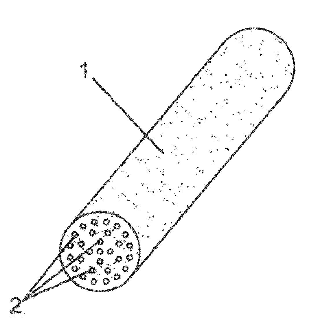
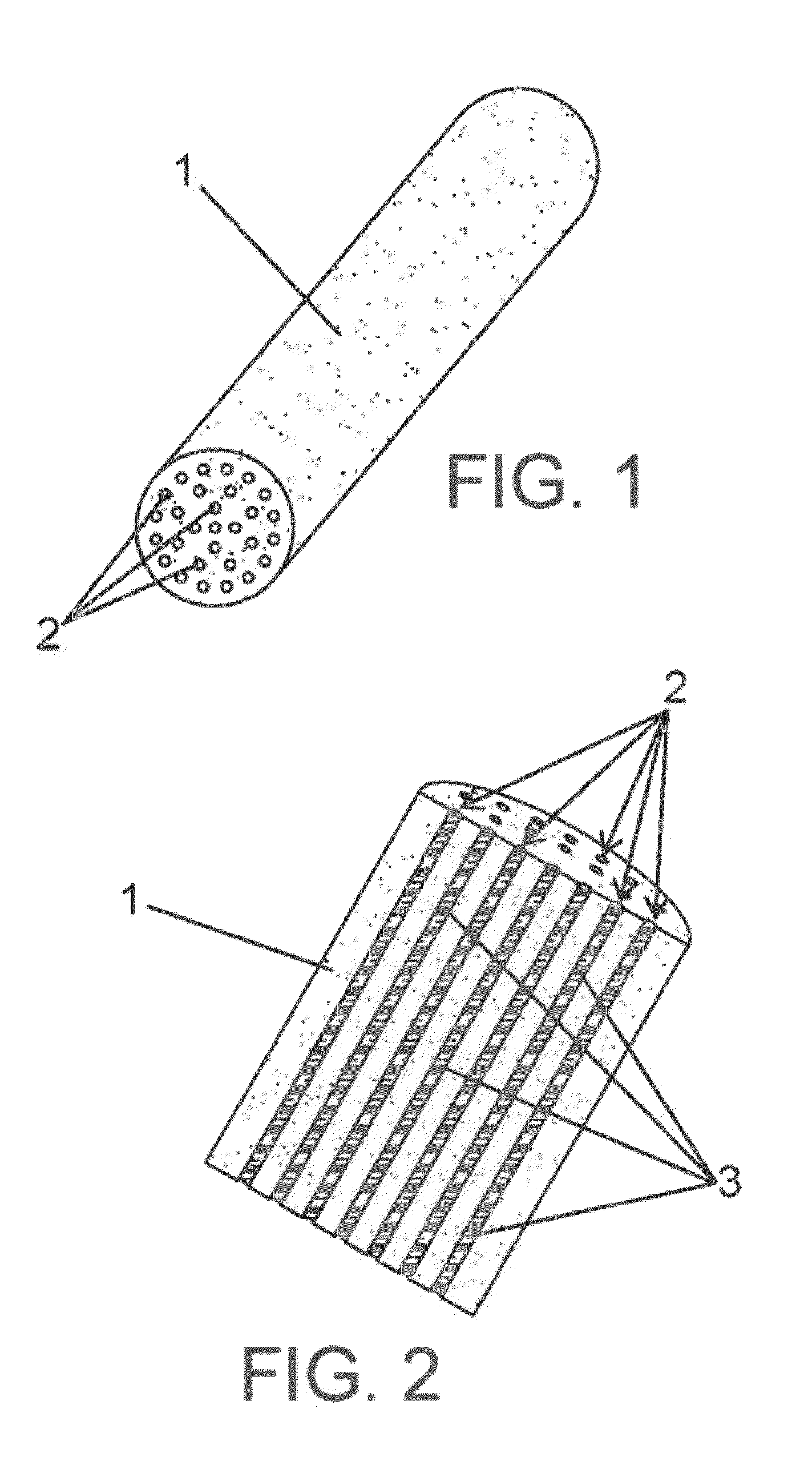
[0029]FIGS. 1 and 2 show a possible embodiment of a ceramic filtration membrane according to the invention.

[0030]The ceramic filtration membrane is formed by a porous support (1) made from a ceramic material having inner channels (2) through which the liquid to be filtered is circulated. As seen in the section view of FIG. 2, ceramic layers (3) acting as a semipermeable physical barrier for separating substances contained in the liquid to be filtered are deposited in the inner channels (2). Therefore, most of the liquid passes through the ceramic filtration membrane by means of the inner channels (2), and a small part of the liquid is filtered through the ceramic layers (3) and the porous support (1); this filtered liquid is referred to as permeate.

[0031]Inorganic filtration membranes have a tubular morphology with a diameter comprised between 10 mm-200 mm and a length of up to 2000 mm.

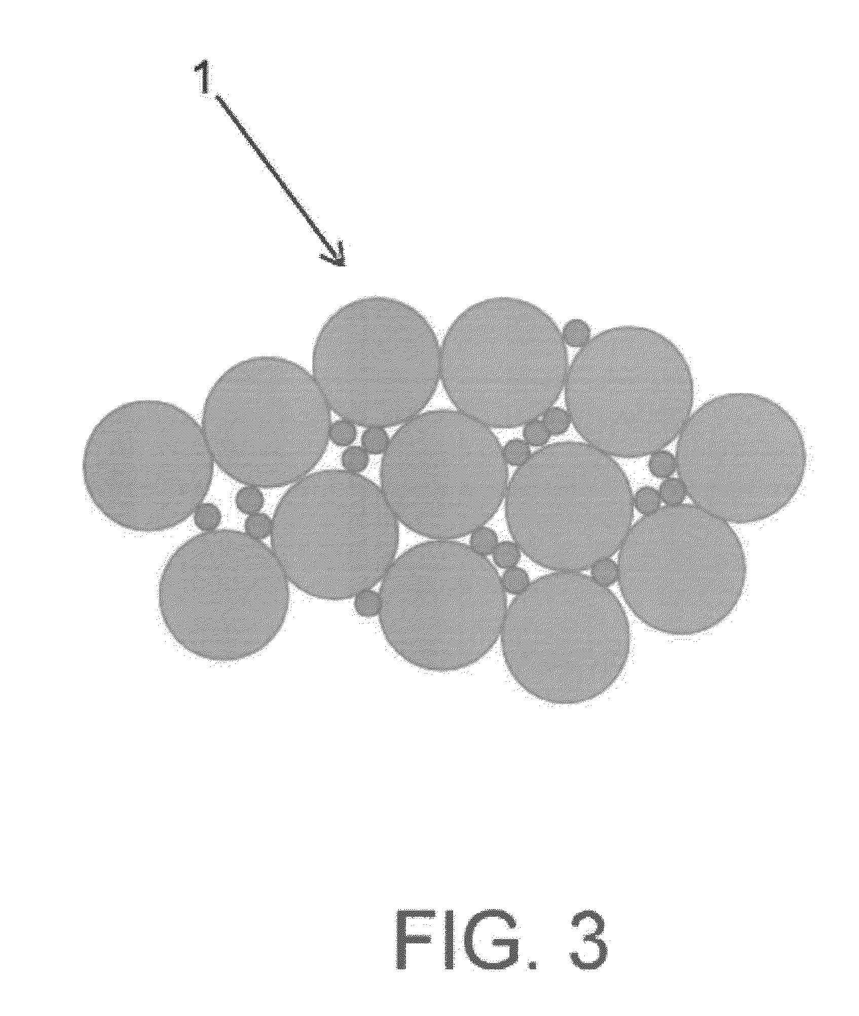
[0032]The porous support (1) is formed by a mixture of aluminum oxide particles (Al2O3) having a d...


PUM

PropertyMeasurementUnit
porosityaaaaaaaaaa
particle sizeaaaaaaaaaa
temperatureaaaaaaaaaa

Abstract

The present invention relates to a ceramic filtration membrane with a porous support (1) formed by sintering aluminum oxide particles and metal oxide particles at a temperature greater than 1300° C. and less than 1500° C., comprising fine aluminum oxide particles with a particle size of less than 10 μm, and coarse aluminum oxide particles with a particle size of 20 μm-150 μm, where the fine aluminum oxide particles represent a percentage by weight. of 3%-10% with respect to the total weight of the porous support (1), the porous support (1) having a porosity greater than 28% with a pore size of 1 μm-7 μm, bending strength greater than 45 MPa and suitable chemical resistance, giving rise to ceramic filtration membranes with ceramic layers (3) having a pore size of 1 nm to 1000 nm.

Description

CROSS REFERENCE TO RELATED APPLICATION[0001]This Application claims the priority of Spanish Patent Application No. 201430334 filed on Mar. 12, 2014, which is incorporated by reference herein.FIELD OF THE ART[0002]The present invention relates to the separation of particles contained in a liquid using filtration or separation elements by means of filtering membranes, proposing a ceramic membrane having a porous ceramic support with a low manufacturing cost and suitable characteristics in terms of filtration, mechanical strength and resistance against chemical etching from cleaning.STATE OF THE ART[0003]Ceramic membranes used for filtration are formed by a porous support made from a ceramic material and on which thin ceramic layers are deposited. The porous support provides the necessary mechanical rigidity for membrane operation and is responsible for supporting the ceramic layers, whereas the ceramic layers work as a semipermeable physical barrier separating substances contained in ...

Claims


Application Information

Patent Timeline
Patent Type & Authority Applications(United States)
IPC IPC(8): B01D71/02B01D67/00B01D69/10C04B33/02C04B33/04
CPCB01D71/025C04B33/025B01D67/0083B01D69/10C04B33/04B01D63/066B01D67/0041B01D71/027B01D2325/02B01D2325/24B01D69/00C04B35/10
Inventor LOPETEGUI GARNICA, JAVIERETXEBERRIA URANGA, JONOLLO LOINAZ, JAIONE
Owner LIKUID NANOTEK
Why Eureka
Try Eureka