Quantum computer and quantum computation method

a quantum computer and computation method technology, applied in the field of quantum computers and quantum computation methods, can solve the problem of not knowing the specific structure of a quantum computer containing three or more quantum bits

Inactive Publication Date: 2006-08-03
KK TOSHIBA
View PDF3 Cites 20 Cited by
  • Summary
  • Abstract
  • Description
  • Claims
  • Application Information

AI Technical Summary

Problems solved by technology

However, Xiao et al. suggest nothing about the specific structure of a quantum computer containing three or more quantum bits.
Moreover, even if a researcher in this technical field has mastered the methods proposed by Xiao et al., it is still not obvious for them to contrive any specific structure of the quantum computer containing three or more quantum bits.

Method used


Image

  • Quantum computer and quantum computation method
  • Quantum computer and quantum computation method
  • Quantum computer and quantum computation method

Examples


example 1

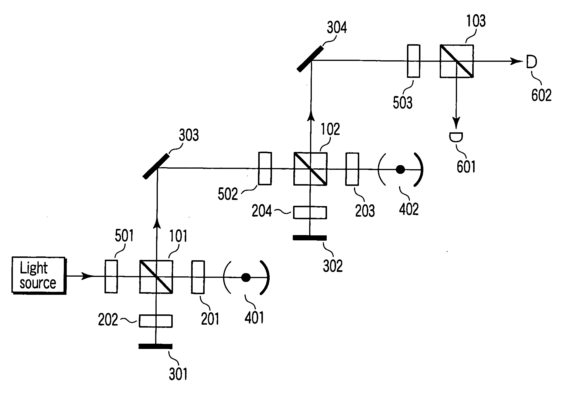
[0126] Referring to FIG. 13, a description will be given of an example of the CZ gate on atomic and photonic quantum bits shown in FIG. 1.

[0127] To confirm whether a CZ gate therebetween is realized or not, bit reading previously described with reference to FIG. 10 is performed. Explaining in more detail, first an atom is preset in a certain known state, then the process shown in FIG. 10 is performed on the atom to measure the state of the atom, and finally it is verified that the measured state corresponds to the preset certain state. When the CZ gate and the bit reading have succeeded, a V-polarized light beam is observed if the preset certain state of the atom is |0>. In contrast, if the preset certain state of the atom is 1>, an H-polarized light beam has to be observed. Accordingly, this example can also be regarded as an example of the reading method.

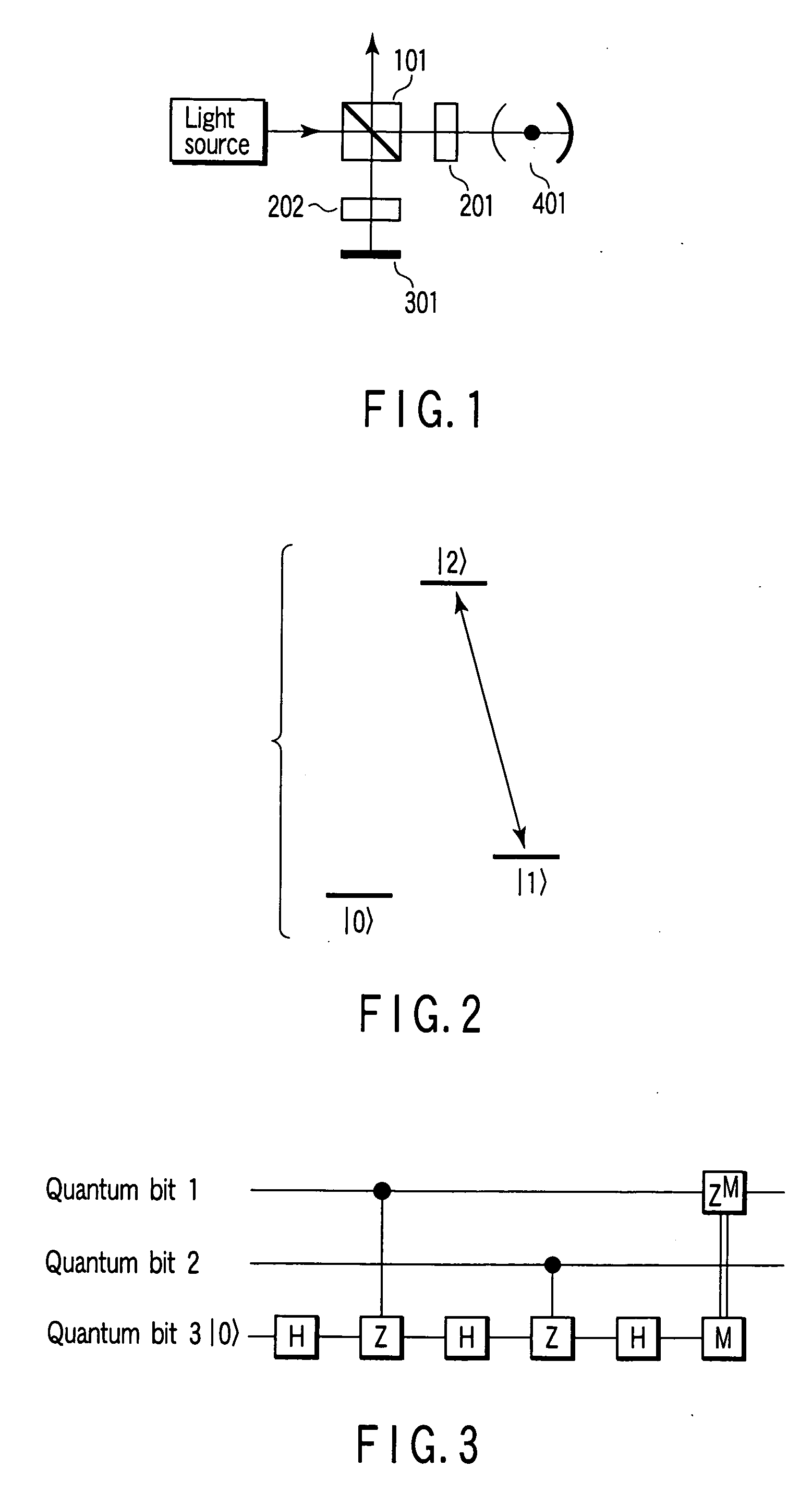
[0128] In example 1, Pr3+ ions contained in Y2SiO5 crystal are used as atoms having such three levels as shown in FIG. 2. The ...

example 2

[0134] In example 2, a single-photon pulse is guided into a cavity, unlike example 1. In example 1, a weak coherent light beam is guided to the cavity. Referring to FIG. 16, a description will be given of a quantum computer, according to example 2, in which a CZ gate operation is performed on an atom and a photon using a single-photon pulse.

[0135] The right side system of FIG. 16 (i.e., the optical systems located rightward with respect to the PBS 101, acoustooptic modulator 1204 and beam splitter 1008) are similar to those employed in example 1 of FIG. 13 except that the incident light beam is a single-photon pulse. The left side system of FIG. 16 (including the PBS 101, acoustooptic modulator 1204 and beam splitter 1008) are used to generate a single-photon pulse. An optical cavity 1301 included in the left side system is similar to an optical cavity 1302 for a CZ gate.

[0136] A method for generating a single-photon pulse using the left side system will be described. Firstly, a s...

example 3

[0138] Referring to FIG. 17, a description will be given of example 3 related to a CZ gate between two atoms.

[0139] Since it is necessary to guide a light beam to a cavity 1302 to lastly read the state of an atom in the cavity 1302, an optical system including a cavity 1301 is coupled with an optical system including the cavity 1302 via a ring cavity. As shown in FIG. 17, the ring cavity comprises high reflection mirrors 305 and 306, input mirrors 801 and 802, and cavity length adjuster 901.

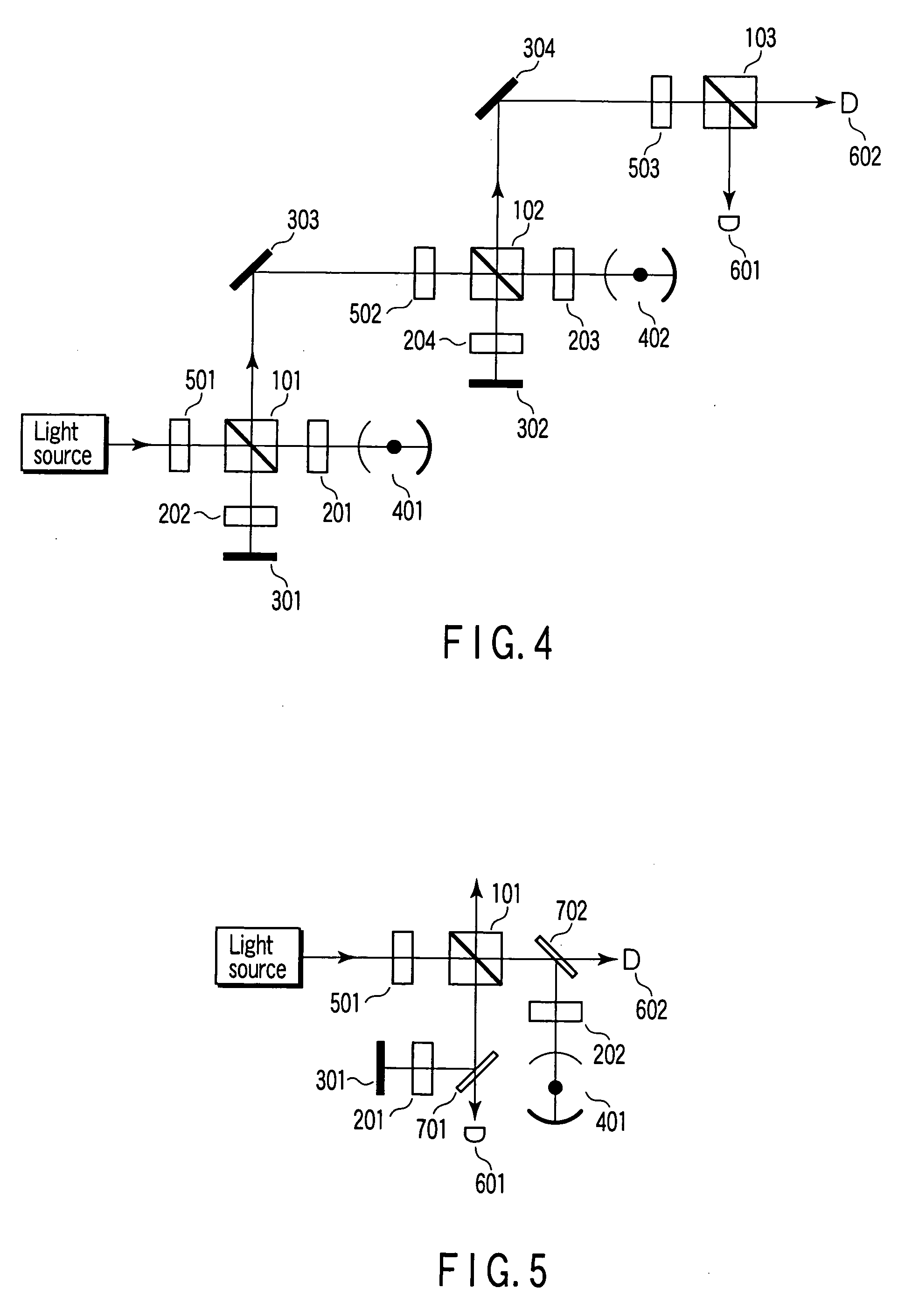
[0140] Further, the quantum computer shown in FIG. 17 is fundamentally similar in structure to the CZ gate with extensibility shown in FIG. 7, therefore example 3 can also be regarded as an example of the CZ gate with extensibility.

[0141] In example 3, to confirm whether a CZ gate operation between two atoms has succeeded, the fact is noticed that a control NOT gate (CNOT) operation can be performed by three gate operations−(an H gate operation on a target bit)→a CZ gate operation→(an H gate o...


PUM

PropertyMeasurementUnit
waist radiusaaaaaaaaaa
cavity lengthaaaaaaaaaa
resonant frequencyaaaaaaaaaa

Abstract

Quantum computer includes optical systems arranged in series each of the plurality of optical systems includes first half-wave plate, first polarizing beam splitter, first switching mirror, first photodetector, first polarization rotator, optical cavity which contains atom, second switching mirror, second photodetector, second polarization rotator, and high reflection mirror, first polarization beam splitter outputting third light beam received from first switching mirror or second switching mirror to adjacent one of optical systems, third switching mirrors each provided between adjacent two optical systems, each of third switching mirrors reflecting or transmitting light beam output from one of two optical systems, light sources each providing light beam to corresponding optical system, and measurement system which measures polarization of incoming light beam.

Description

CROSS-REFERENCE TO RELATED APPLICATIONS [0001] This application is based upon and claims the benefit of priority from prior Japanese Patent Application No. 2005-026654, filed Feb. 2, 2005, the entire contents of which are incorporated herein by reference. BACKGROUND OF THE INVENTION [0002] 1. Field of the Invention [0003] The present invention relates to a quantum computer and quantum computation method utilizing coupling of an optical cavity with an atom. [0004] 2. Description of the Related Art [0005] L.-M. Duan et al. have proposed a new method for realizing a controlled phase flip gate (see, for example, L.-M. Duan and H. J. Kimble, Phys. Rev. Lett. 92, 127902 (2004)). In this proposal, quantum bits are expressed by polarization of photons. However, in quantum computers, it is preferable to express quantum bits using atomic states that are more stable and easily usable as memories. [0006] In light of this, Y.-F. Xiao et al. have proposed a controlled phase flip gate in which a c...

Claims


Application Information

Patent Timeline
Patent Type & Authority Applications(United States)
IPC IPC(8): G02F1/01G06N99/00
CPCB82Y10/00G06N99/002G06N10/00
Inventor GOTO, HAYATOICHIMURA, KOUICHI
Owner KK TOSHIBA
Why Eureka
Try Eureka