Sensor devices for structural health monitoring

a sensor device and structural health technology, applied in the field of sensor technology, can solve the problems of inability to provide suitable monitoring solutions, large structures including metal elements, and often prone to metal corrosion, and achieve the effect of improving structural health monitoring

Inactive Publication Date: 2006-08-03
YASUMI CAPITAL
View PDF70 Cites 134 Cited by
  • Summary
  • Abstract
  • Description
  • Claims
  • Application Information

AI Technical Summary

Benefits of technology

[0009] In one aspect, the present invention is applied to monitoring the health of roadways, bridges or portions thereof such as bridge decks. A device comprising a sensor is embedded in the concrete and measures local chloride concentration. When polled by a suitable interrogator, the device outputs a signal corresponding to the chloride concentration. For example, the interrogator may pole the device using an RF signal. Using circuitry that quickly responds to the interrogation signal, the present invention enables real-time communication with an embedded sensor. Each device may be uniquely identified with a number or code stored in a microchip, for example. Interrogation of numerous devices in proximity may use anticollision algorithms and RFID technology. A database may be constructed for a sensor array in a roadway or bridge. The database may be used to track polling results over time for a single bridge—and allow for convenient comparison of the health status for numerous bridges. Applying interrogation to hundreds and thousands of bridges provides an automated and simplified tool to help maintenance technicians prioritize maintenance schedules for a large number of bridges. In one embodiment, the devices are passive and derive power from the RF illumination, thereby alleviating the need for battery power and battery maintenance so that the embedded sensor devices may last as long as the bridge or bridge deck.
[0010] Real-time communication with an embedded sensor permits the interrogator to be placed on a truck or moving vehicle, and polling of numerous similar devices embedded in multiple locations of a bridge deck to be performed as the truck drives over each device. For roadway maintenance programs, vehicular interrogation in this manner offers simplified and expeditious polling compared to conventional manual techniques.
[0012] To keep the sensor device small and simple, it may be passive—that is, it does not require a self-contained continual power source for operation (such as a battery). This also extends device longevity. Thus, components included in the device such as a sensor and transponder may be passive. In one example described, a radio frequency interrogation signal may provide the transponder power.
[0019] The present invention finds use in a wide range of applications. The use of an identification code with each recording device allows for monitoring large structures having many spatially separated points that are to be individually monitored.

Problems solved by technology

Many large structures are prone to degradation over time.
For example, a large structure including metal elements, such as an aircraft or concrete structure with metal reinforcement, is often susceptible to metal corrosion.
Conventional sensing techniques frequently do not provide suitable monitoring solutions for monitoring the health of a large structure.
This is not permissible according to conventional techniques.
Pavement and concrete exposed to heavy traffic and weathering deteriorate over time.
Over time, the amount of chloride in the concrete increases and may reach levels that substantially attack and corrode the metal elements.
Steel rebar for example will corrode in the presence of chloride ions at known critical levels.
The resulting corrosion leads to expansion of the rebar volume and cracking of the concrete.
Not only highly time-consuming, costly, and prone to confusion, this method also aggravates the same problem it intends to detect and prevent.
These manual techniques may also contribute to traffic congestion.
Moreover, it typically takes years for a critical chloride concentration to be reached, so a large number of these inefficient manual tests may be required.

Method used


Image

  • Sensor devices for structural health monitoring
  • Sensor devices for structural health monitoring
  • Sensor devices for structural health monitoring

Examples


Embodiment Construction

[0043] The present invention will now be described in detail with reference to a few preferred embodiments thereof as illustrated in the accompanying drawings. In the following description, numerous specific details are set forth in order to provide a thorough understanding of the present invention. It will be apparent, however, to one skilled in the art, that the present invention may be practiced without some or all of these specific details. In other instances, well known process steps and / or structures have not been described in detail in order to not unnecessarily obscure the present invention.

Structural Health Monitoring

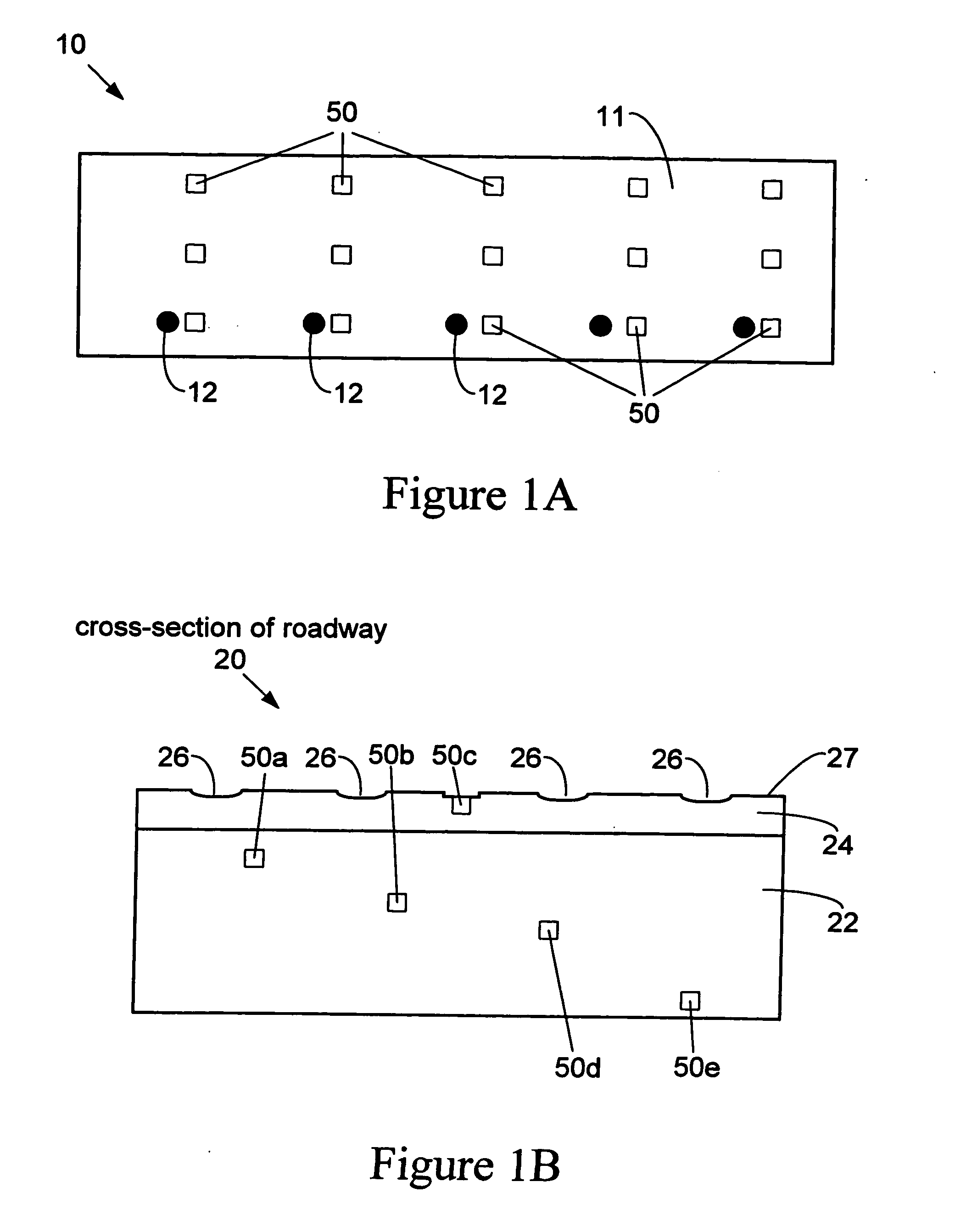
[0044] The present invention is well suited to monitor the health of a large structure or portion thereof. FIG. 1A illustrates a structure portion 10 may be included as part of a building, bridge, road, etc and comprises concrete 11 and metal 12. An array of sensing devices 50 are embedded in structure portion 10 and detect a parameter indicative of the heal...


PUM

PropertyMeasurementUnit
tensile stressaaaaaaaaaa
operational depthaaaaaaaaaa

Abstract

Described herein are wireless interrogation systems and methods that rely on a complementary sensing device and interrogator. The sensing device is disposed to measure a parameter indicative of the health of a structure. A sensor reading from the sensor indicates the level of a parameter being monitored or whether one or more particular physical or chemical events have taken place. Using wireless techniques, the interrogator probes the device to determine its identity and its current sensor reading. This often includes transmission of a wireless signal through portions of the structure. When activated, the device responds with a wireless signal that identifies the device and contains information about the parameter being measured or a particular sensor state corresponding to the parameter. The identity of the device allows it to be distinguished from a number of similar devices. Thus this invention finds particular usefulness in the context of an array of devices that can be probed by a wireless interrogation unit. In one embodiment, the devices are passive and derive power from the interrogation signal.

Description

CROSS-REFERENCE TO RELATED APPLICATIONS [0001] This application claims priority under U.S.C. §120 from co-pending U.S. patent application Ser. No. 10 / 115,872, filed Apr. 3, 2002 and entitled, “SENSOR DEVICES FOR STRUCTURAL HEALTH MONITORING”, which is incorporated herein for all purposes and which claims priority under U.S.C. §120 from patent application entitled “Wireless Event Recording Devices With Identification Codes” by David G. Watters et al., filed on Feb. 26, 1999 (U.S. application Ser. No. 09 / 258,073), which is incorporated by reference herein.BACKGROUND OF THE INVENTION [0002] The present invention relates generally to sensor technology. More particularly, the present invention relates to sensing devices and systems used to monitor large structures using wireless communication techniques. [0003] Many large structures are prone to degradation over time. For example, a large structure including metal elements, such as an aircraft or concrete structure with metal reinforceme...

Claims


Application Information

Patent Timeline
Patent Type & Authority Applications(United States)
IPC IPC(8): H04Q5/22E01D22/00G01D5/48G01K3/04G01K5/48G01M5/00G01N27/416G08C17/00
CPCG01D5/48G01D21/00G01K3/04G01K5/483G01M5/0008G01M5/0041G01M5/0083G01M5/0091G06K19/0717E01D22/00H04Q2209/47G01N27/4035H04Q9/00H04Q2209/823
Inventor WATTERS, DAVID G.HUESTIS, DAVID L.BAHR, ALFRED J.PRIYANTHA, NAMALJAYAWEERA, PALITHA
Owner YASUMI CAPITAL
Why Eureka
Try Eureka