Planar light source device and liquid crystal display apparatus

Inactive Publication Date: 2006-08-03
TOSHIBA MATSUSHITA DISPLAY TECH
View PDF3 Cites 0 Cited by
  • Summary
  • Abstract
  • Description
  • Claims
  • Application Information

AI Technical Summary

Benefits of technology

[0013] According to the present invention, it is possible to provide a planar light source device which has sufficient stiffness against external force, and a liquid crystal display apparatus including the planar light source device. Further, according to the present invention, it is

Problems solved by technology

However, it is difficult to ensure sufficient stiffness of the planar light source device of the area light system, because of its structure.
However, if the upper surface cover is attached to the back surface cover as described above, the shorter sides of the back surface cover cannot be fixed.
Therefore, sufficient stiffness against external force applied to the planar light source

Method used


Image

  • Planar light source device and liquid crystal display apparatus
  • Planar light source device and liquid crystal display apparatus
  • Planar light source device and liquid crystal display apparatus

Examples


Embodiment Construction

[0021] A liquid crystal display apparatus according to an embodiment of the present invention will be described with reference to the accompanying drawings.

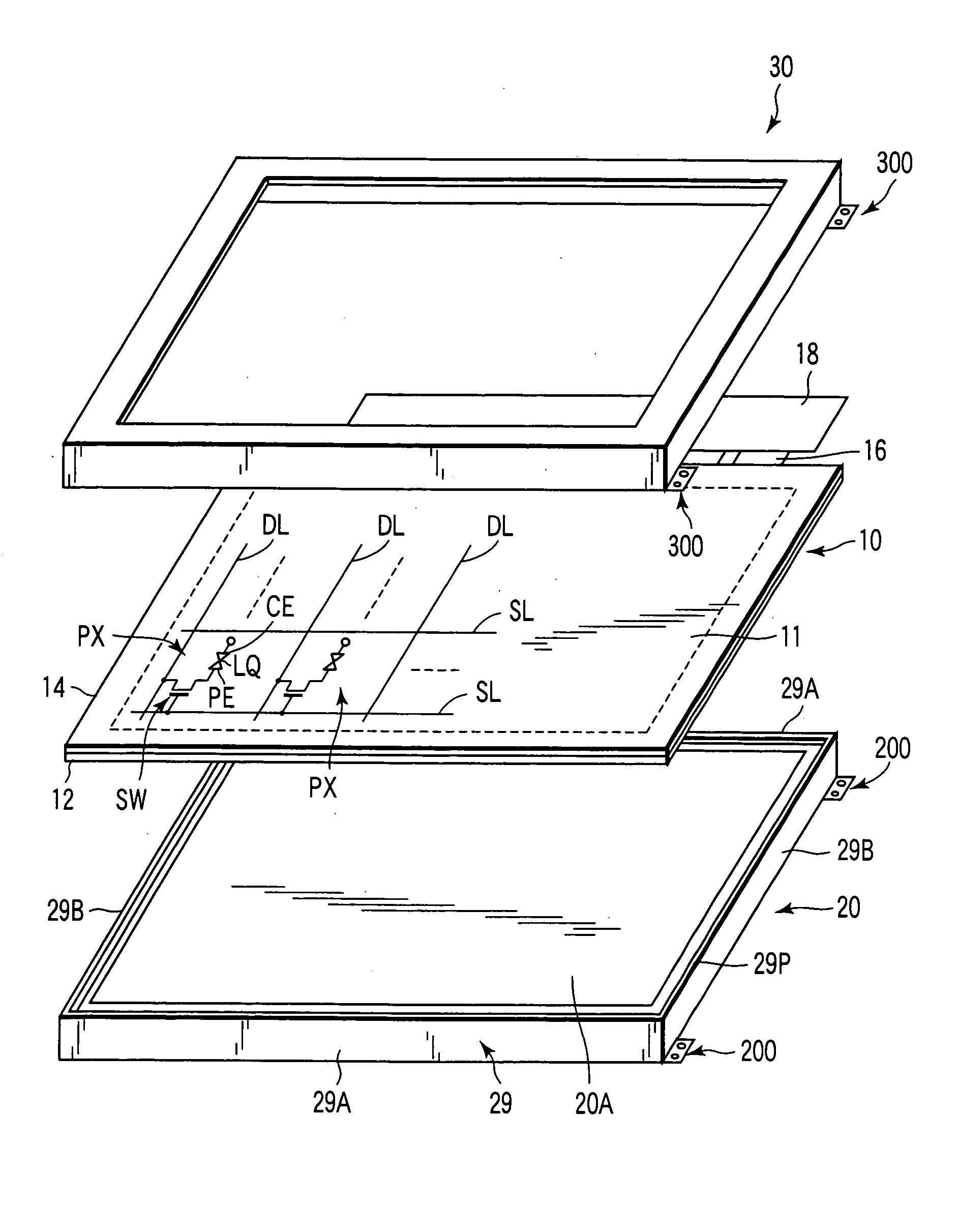
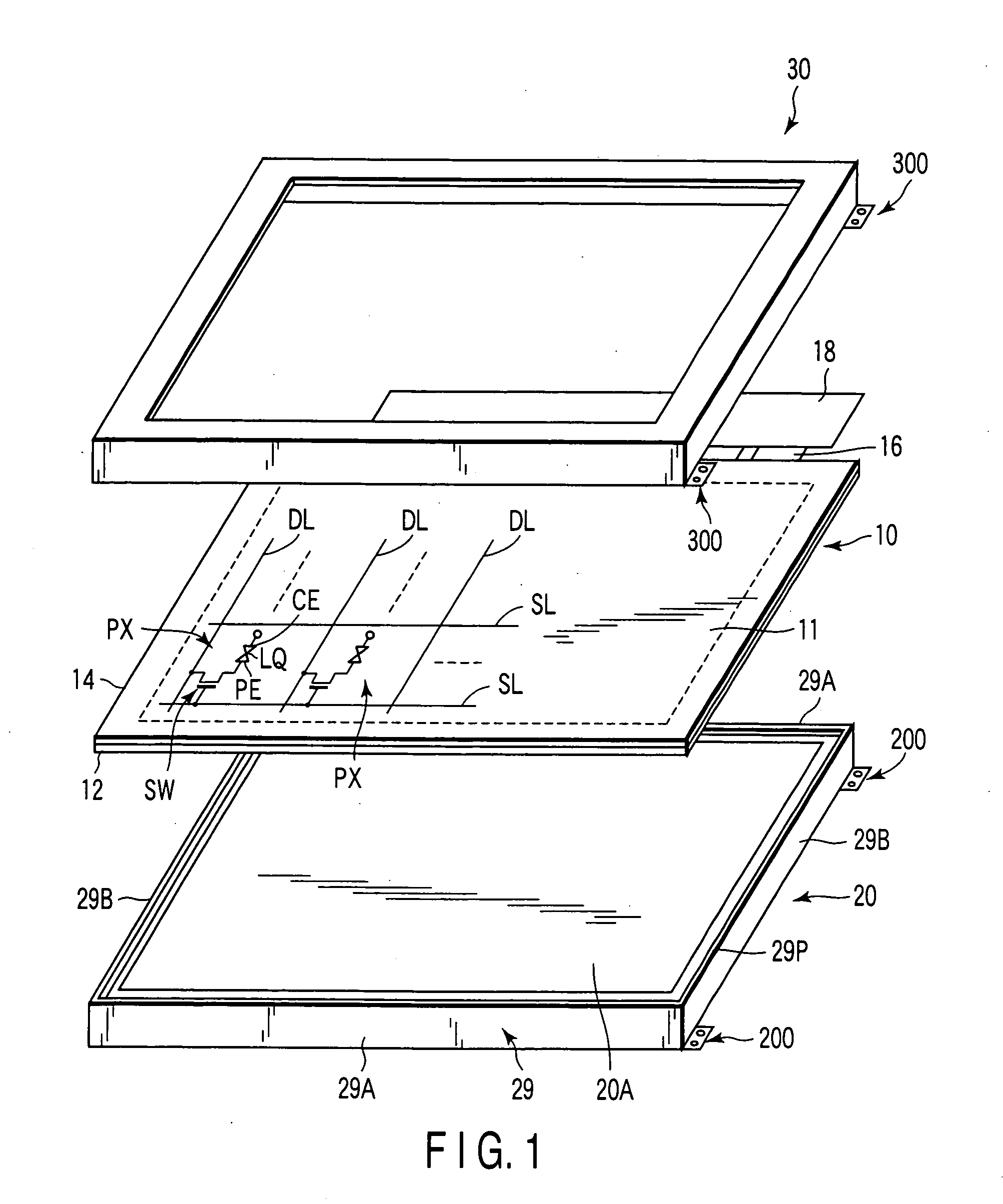
[0022] As shown in FIG. 1, the liquid crystal display apparatus comprises a liquid crystal display panel 10, a planar light source device 20 which illuminates the liquid crystal display panel 10 from behind it (from the side of an array substrate 12 described later), and a frame 30, which is attached to the liquid crystal display panel 10 from above it. The planar light source device 20 and the frame 30 respectively have attachment portions 200 and 300 to be attached to an external unit (for example, a housing of a television unit).

[0023] The liquid crystal display panel 10 comprises a pair of substrates which are arranged opposite to each other; that is, an array substrate 12 and a counter substrate 14. It also comprises a liquid crystal layer LQ, which is sandwiched between the array substrate 12 and the counter substrate 14....


PUM


Abstract

A liquid crystal display apparatus includes a liquid crystal display panel including a display region in which a plurality of pixels are arrayed, and a planar light source device which illuminates the liquid crystal display panel from behind it. The planar light source includes cold cathode fluorescent tubes, a back surface cover, which is substantially rectangular and stores the cold cathode fluorescent tubes, and an upper surface cover attached to the back surface cover. The back surface cover has at least two extended portions, each having a main body portion extending from a side of the back surface cover and a lug portion protruding from the main body portion. The upper surface cover has supporting portions, each supporting at least the lug portion of each extended portion.

Description

CROSS-REFERENCE TO RELATED APPLICATIONS [0001] This application is based upon and claims the benefit of priority from prior Japanese Patent Application No. 2005-023792, filed Jan. 31, 2005, the entire contents of which are incorporated herein by reference. BACKGROUND OF THE INVENTION [0002] 1. Field of the Invention [0003] The present invention relates to a planar light source device and a liquid crystal display apparatus. In particular, the present invention relates to a planar light source device of an area light system, which does not comprises a light guide and but has a light source facing an object to be illuminated, and to a liquid crystal display apparatus comprising the planar light source device. [0004] 2. Description of the Related Art [0005] In recent years, a liquid crystal display apparatus, which displays images on a liquid crystal display panel, has been widely used as a display of a personal computer or the like. Lately, as liquid crystal screen TV sets have come in...

Claims


Application Information

Patent Timeline
IPC IPC(8): G02F1/1335
CPCG02F1/133608G06F1/1613
Inventor SHIMIZU, MAKOTOURA, TOSHIHIKOYASUDA, YOSHINORIKANEDA, HIROMI
Owner TOSHIBA MATSUSHITA DISPLAY TECH
Why Eureka
Try Eureka