Digital phase detector for a phase locked loop

Active Publication Date: 2006-08-03
SKYWORKS SOLUTIONS INC
View PDF11 Cites 38 Cited by
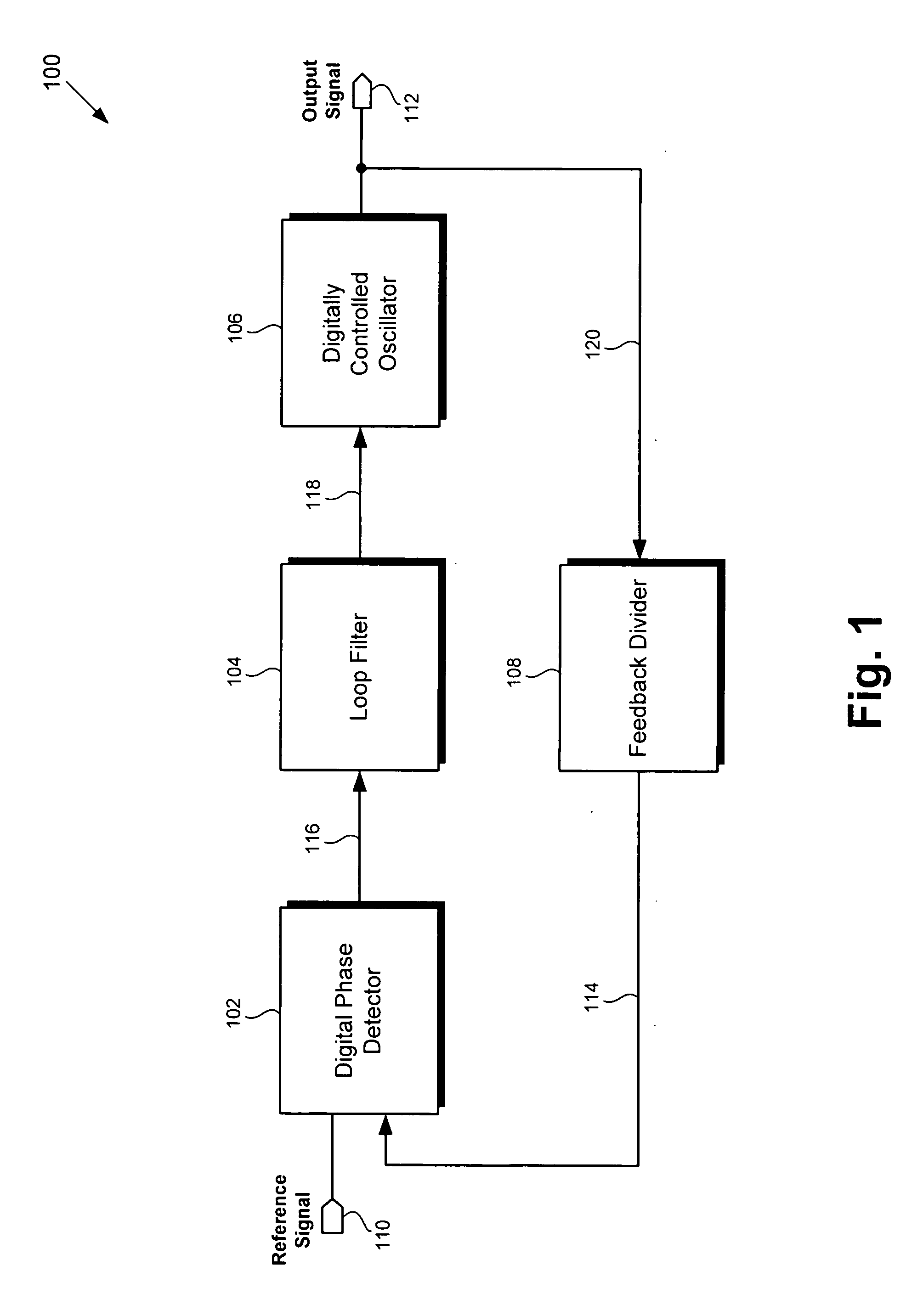
  • Summary
  • Abstract
  • Description
  • Claims
  • Application Information

AI Technical Summary

Benefits of technology

[0007] The present invention is directed to a digital phase detector for a phase locked loop. The present invention resolves the need in the art for a digital phase detector for a phase locked loop that overcomes the deficiencies of conventional phase detectors.
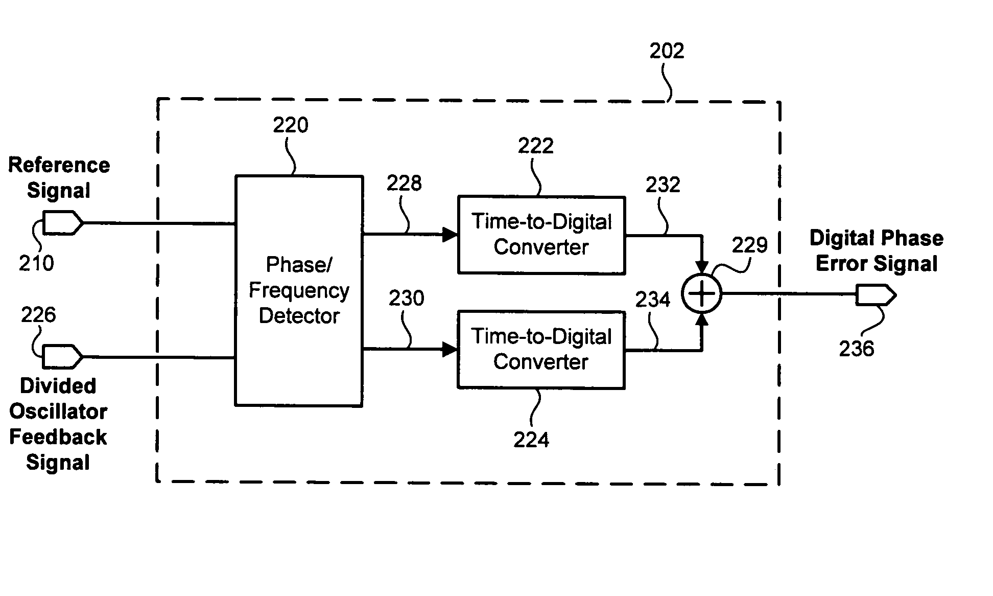
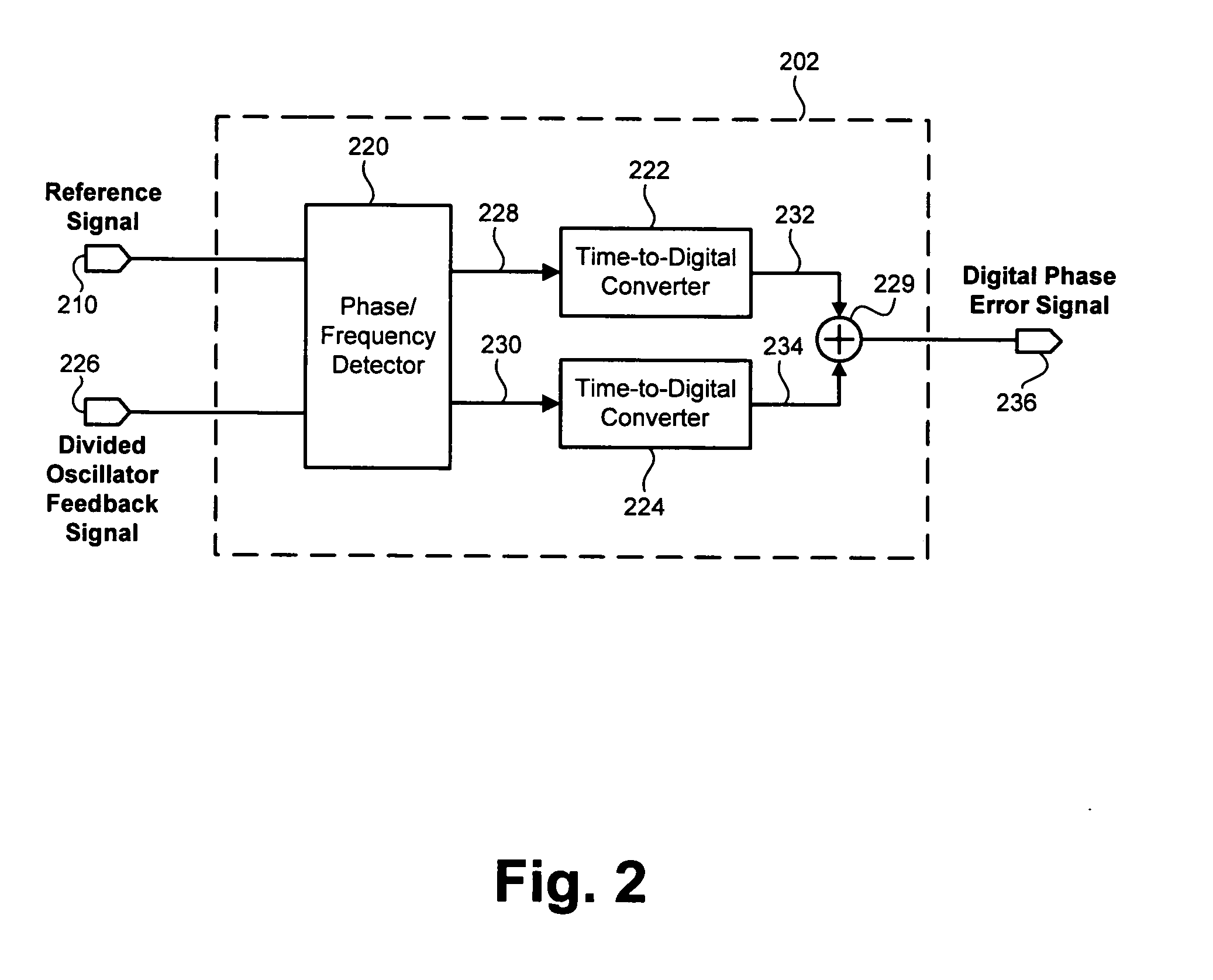
[0008] According to one exemplary embodiment, a digital phase detector includes a phase/frequency detector, where the phase/frequency detector is configured to receive a reference signal and a divided oscillator feedback signal and output a first pulse-width modulated signal and a second pulse-width modulated signal. The first pulse-width modulated signal can indicate that a phase of the divided oscillator feedback signal leads a phase of the reference signal, for example. The second pulse-width modulated signal can indicate that a phase of the divided oscillator feedback signal lags a phase of the reference signal, for example. An output of the digital phase detector can control a frequency of an output signal of a digitally controlled oscillator, for example. The digital phase detector also includes a first time-to-digital converter, where the first ti

Problems solved by technology

However analog phase detectors suffer from the traditional limitations of analog circuitry, such as variation with process, temperature dependence, sensitivity to substrate coupl

Method used


Image

  • Digital phase detector for a phase locked loop
  • Digital phase detector for a phase locked loop
  • Digital phase detector for a phase locked loop

Examples


Embodiment Construction

[0012] The present invention is directed to a digital phase detector for a phase locked loop. The following description contains specific information pertaining to the implementation of the present invention. One skilled in the art will recognize that the present invention may be implemented in a manner different from that specifically discussed in the present application. Moreover, some of the specific details of the invention are not discussed in order not to obscure the invention. The specific details not described in the present application are within the knowledge of a person of ordinary skill in the art.

[0013] The drawings in the present application and their accompanying detailed description are directed to merely exemplary embodiments of the invention. To maintain brevity, other embodiments of the invention which use the principles of the present invention are not specifically described in the present application and are not specifically illustrated by the present drawings....


PUM


Abstract

According to one exemplary embodiment, a digital phase detector includes a phase/frequency detector, where the phase/frequency detector is configured to receive a reference signal and a divided oscillator feedback signal and output a first pulse-width modulated signal and a second pulse-width modulated signal. The digital phase detector also includes a first time-to-digital converter, where the first time-to-digital converter is coupled to the phase/frequency detector. The first time-to-digital converter is configured to receive and convert the first pulse-width modulated signal to a first digital number. The digital phase detector further includes a second time-to-digital converter coupled to the phase/frequency detector and configured to receive and convert the second pulse-width modulated signal to a second digital number. The digital phase detector further includes a summation element, where the summation element is configured to subtract the second digital number from the first digital number and output a digital phase error signal.

Description

BACKGROUND OF THE INVENTION [0001] 1. Field of the Invention [0002] The present invention is generally in the field of electrical circuits. More particularly, the invention is in the field of phase locked loops. [0003] 2. Related Art [0004] Phase locked loops are often used as frequency synthesizers in applications, such as communication systems, that require a precise signal frequency. The typical components of a phase locked loop include a phase detector, a frequency-controllable oscillator, and a loop filter. Phase detectors, such as a charge pump phase detector and a sample-and-hold phase detector, are commonly implemented using analog circuitry. However analog phase detectors suffer from the traditional limitations of analog circuitry, such as variation with process, temperature dependence, sensitivity to substrate coupling, and limitations caused by parasitics. [0005] Various approaches to digital phase detection have been attempted to overcome the above limitations of phase d...

Claims


Application Information

Patent Timeline
IPC IPC(8): H03D3/24
CPCH03D13/003H03L7/085H03D3/24H03L7/08
Inventor YOUSSOUFLAN, EDWARD
Owner SKYWORKS SOLUTIONS INC
Why Eureka
Try Eureka