
Electric potential measuring device using oscillating device, image forming apparatus, and electric potential measuring method

a technology of electric potential and measuring device, which is applied in the direction of electrographic process apparatus, instruments, and electrostatic field measurements, etc., can solve the problems of unsolved size and cost reduction problems, easy influence of external noise on the output signal of the sensor, and small sensor output current “i” also, etc., to achieve high sensitivity, high sensitivity, and high measuring accuracy.

Inactive Publication Date: 2006-08-03
CANON KK
View PDF25 Cites 29 Cited by
  • Summary
  • Abstract
  • Description
  • Claims
  • Application Information

AI Technical Summary

Benefits of technology

[0015] Accordingly, with the view of overcoming the problems mentioned above, an object of the present invention is to provide an electric potential measuring device, an image forming apparatus, and an electric potential measuring method, which are useful in realizing size reduction, high sensitivity and high reliability.
[0016] To achieve the above object, there is provided an electric potential measuring device including: an oscillating device which includes torsion springs, and an oscillating body axially supported by the torsion springs such that the oscillating body oscillates about the torsion springs; and signal detecting means which is located on a surface of the oscillating body and includes at least one detection electrode, in which an output signal appearing on the detection electrode is detected by varying a distance between the detection electrode and a surface of an electric potential measuring object disposed facing the detection electrode by the oscillating device to vary a capacitance between the detection electrode and the surface of the electric potential measuring object. As understood from the related art description, to vary the capacitance between the surface of the electric potential measuring object, such as a photosensitive drum, and an electric potential sensor (detection electrode) as the electric potential measuring device, any of the following (1) to (3) is varied: (1) distance between the surface of the potential measuring object and the detection electrode, (2) dielectric constant of a material between them, and (3) facing area between them. In the present invention, the above-mentioned (1) is varied; the detection electrode is typically provided on the periodically oscillating body, and control to vary the distance between the detection electrode and the surface of the electric potential measuring object is carried out. Such electric potential measuring device allows easy designing of a configuration in which the oscillating body oscillates at a high frequency by appropriately selecting torsional rigidity of the torsion spring and a configuration of the oscillating body and others. Further, even if the oscillating body is small, it is easy to achieve a configuration in which a plurality of detection electrodes are provided on the surface of the oscillating body, and signals outputted from the electrodes are appropriately processed (that is, design flexibility is high). With those features, even if the electric potential measuring device is small in size, an electric potential on the surface of the electric potential measuring object can be measured with relatively high measuring accuracy, sensitivity, and reliability.
[0020] According to another aspect of the present invention, there is provided an image forming apparatus including the electric potential measuring device and image forming means, in which a surface of the oscillating body of the electric potential measuring device is disposed facing a surface of an electric potential measuring object of the image forming means, and the image forming means controls an image forming process by using the signal detection result from the electric potential measuring device. The image forming means may contain a copying function, a printing function or a facsimile function. The image forming means includes a photosensitive drum that rotates about a predetermined axis, and a potential on a surface of the photosensitive drum is measured by using the electric potential measuring device. Also in the image forming apparatus, the advantageous features of the electric potential measuring device is efficiently utilized.
[0022] As described above, the output signal appearing on the detection electrode is detected by varying the distance between the detection electrode disposed on the surface of the oscillating body and the surface of the electric potential measuring object disposed facing the detection electrode by the oscillating body to vary the capacitance between the surface of the detection electrode and the surface of the electric potential measuring object. Therefore, design flexibility is relatively high, and even if the electric potential measuring device is small in size, the potential on the surface of the measuring object can be measured with relatively high measuring accuracy, sensitivity, and reliability. Specifically, the oscillating frequency, the area of the detection electrode, and the layout of the detection electrodes can flexibly be determined by appropriately selecting the rigidity of the torsion spring, the shape, length, cross sectional area and others of the oscillating body axially supported by the torsion springs. Accordingly, the sensitivity, accuracy and reliability as required upon occasion are easily realized. Further, the oscillating body can be driven at high frequency by utilization of the resonance frequency. Therefore, the device of high sensitivity is realized. Furthermore, the electrodes of the signal detecting means, the circuit and part of the drive device, and the oscillating body may be unitarily formed. As a result, the electric potential measuring device being small in size and low in cost can easily be realized.

Problems solved by technology

As a result, the sensor output current “i” also becomes small, and the output signal from the sensor is easily influenced by external noise.
Thus, problem remains unsolved in terms of the size and cost reduction.

Method used


Image

  • Electric potential measuring device using oscillating device, image forming apparatus, and electric potential measuring method
  • Electric potential measuring device using oscillating device, image forming apparatus, and electric potential measuring method
  • Electric potential measuring device using oscillating device, image forming apparatus, and electric potential measuring method

Examples


first embodiment

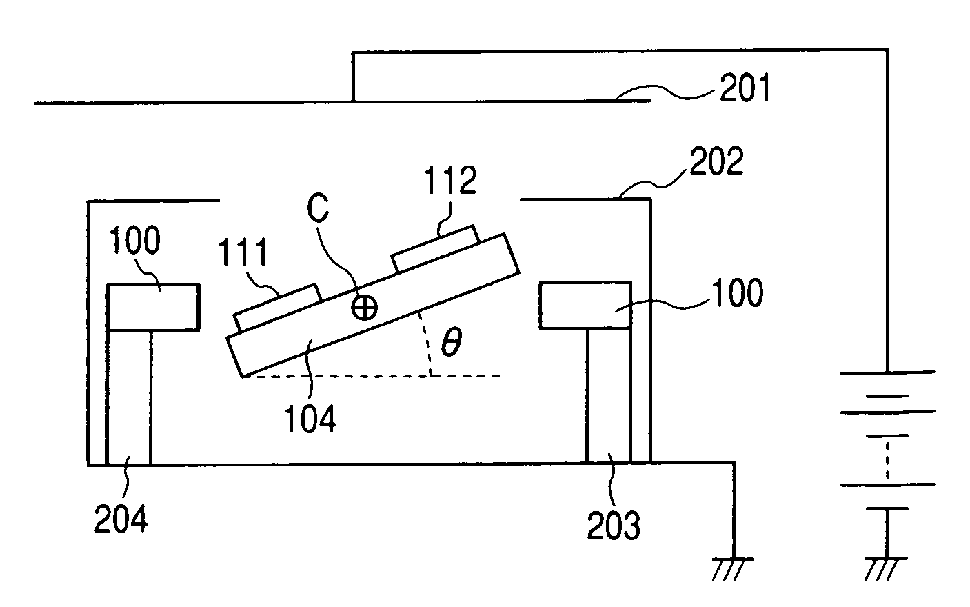
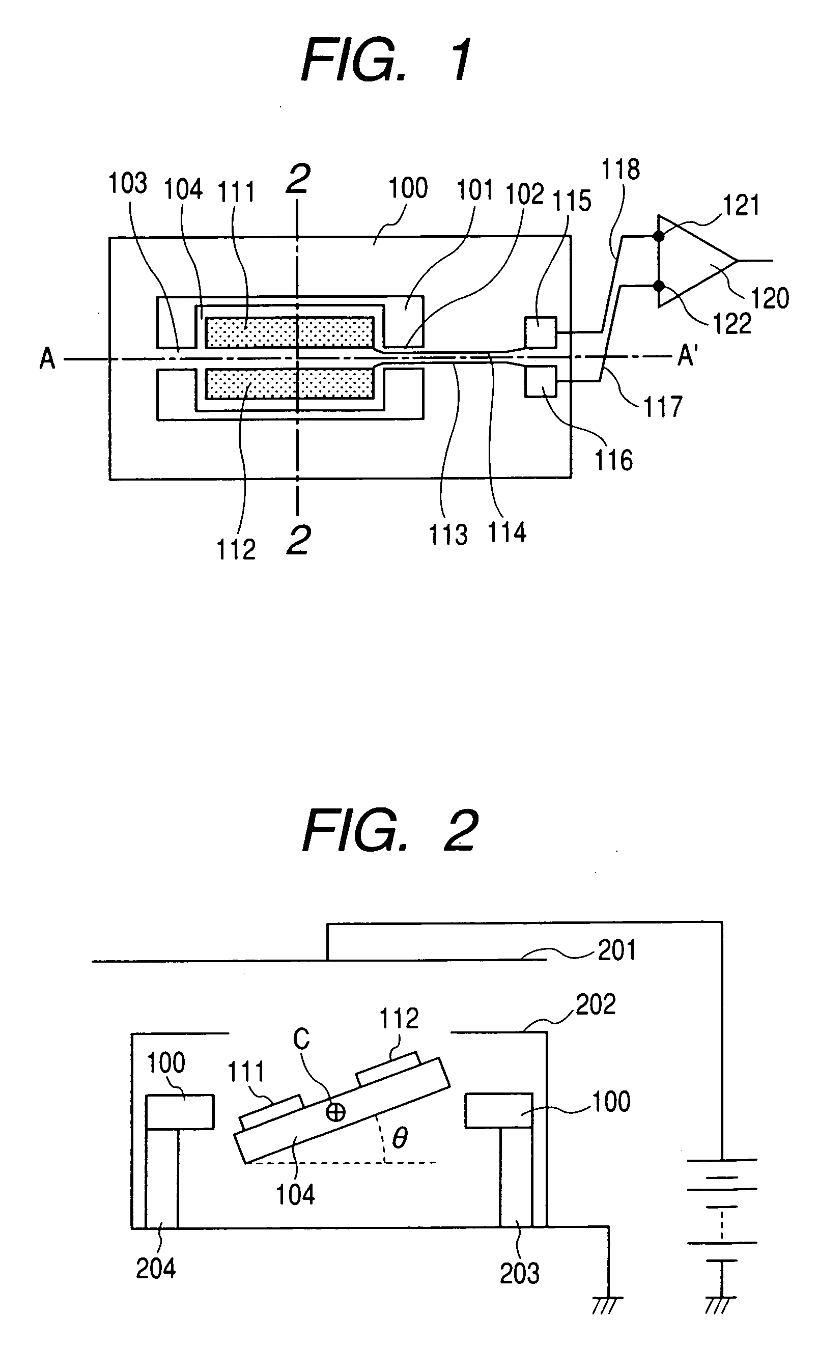
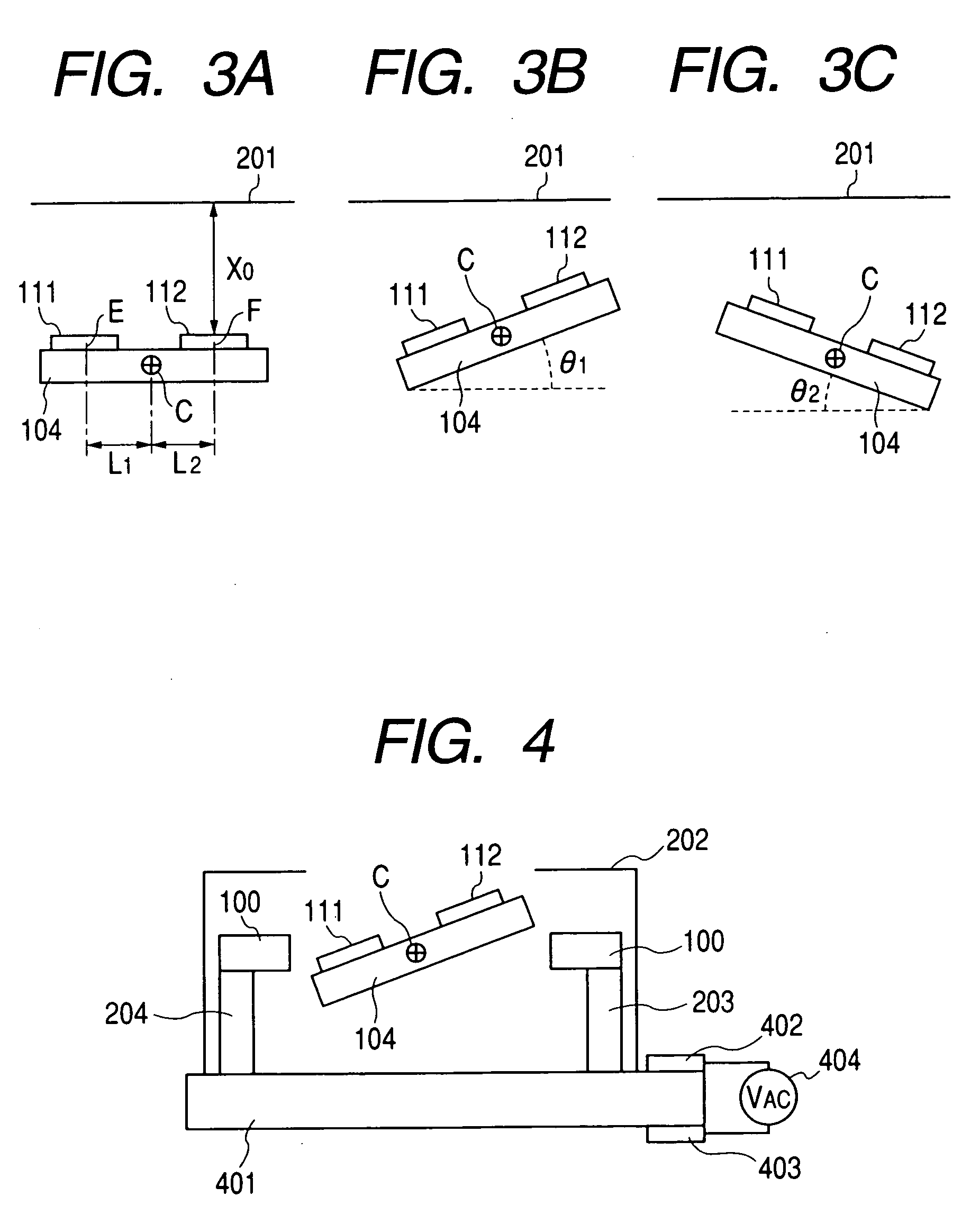
[0032] A first embodiment of the present invention will first be described with reference to FIGS. 1 (if necessary, FIG. 8 which clearly illustrates an opening 101 of a supporting substrate shown in FIG. 1.), 2, 3A to 3C, and 4.

[0033]FIG. 1 shows a construction of an electric potential sensor according to an embodiment of the present invention. An opening 101 is formed at a central part of a supporting substrate 100. A plate-like oscillating body 104 is supported by means of two torsion springs 102 and 103 at a central part of the opening 101. The oscillating body 104 has a structure which is shaped to be line symmetrical with respect to a center line A-A′ connecting the center lines of the torsion springs 102 and 103 as viewed in their major axis direction.

[0034] Two plate-like detection electrodes 111 and 112 being of the same shape are located on one of the surfaces of the oscillating body 104, while being likewise disposed line-symmetrically with respect to the center line A-A...


PUM


Abstract

To provide an electric potential measuring device which is useful in realizing size reduction, high sensitivity, and high reliability. The electric potential measuring device includes: an oscillating device which includes torsion springs, and an oscillating body axially supported by the springs to oscillate; and signal detecting unit which is located on a surface of the oscillating body. A capacitance between the detection electrode and a surface of an electric potential measuring object is varied by varying a distance therebetween by the oscillating device, whereby an output signal appearing on the detection electrode is detected.

Description

TECHNICAL FIELD [0001] The present invention relates to an electric potential measuring device using an oscillating device, an image forming apparatus, and an electric potential measuring method. BACKGROUND ART [0002] Conventionally, in an image forming apparatus of, for example, the type which has a photosensitive drum and forms an image by an electrophotographic process, it is necessary to appropriately (typically, uniformly) charge a photosensitive drum in any environmental conditions, in order to always secure stable image quality. To this end, charged potential of the photosensitive drum is measured by using an electric potential measuring device (electric potential sensor), and a feedback control is carried out by utilizing a result of the measurement so as to secure uniform electric potential distribution over the photosensitive drum. [0003] For the conventional electric potential sensor, a non-contact electric potential sensor is known, and especially, the electric potential...

Claims


Application Information

Patent Timeline
IPC IPC(8): G03G15/00G01R29/12G03G21/00
CPCG01R29/12G01R29/24
Inventor ICHIMURA, YOSHIKATSUSHIMADA, YASUHIROMIZOGUCHI, YASUSHIZAITSU, YOSHITAKA
Owner CANON KK
Features
  • Generate Ideas
  • Intellectual Property
  • Life Sciences
  • Materials
  • Tech Scout
  • Unparalleled Data Quality
  • Higher Quality Content
  • 60% Fewer Hallucinations
Learn More