Quick change head tooling for blow molding machine

a technology of blow molding machine and tooling, which is applied in the direction of dough shaping, manufacturing tools, food shaping, etc., can solve the problems of increasing manufacturing costs, increasing manufacturing costs, and thin wall thickness of containers, so as to minimize the time required for switching, quick and efficient exchange

Inactive Publication Date: 2006-08-03
VISTEON GLOBAL TECH INC
View PDF20 Cites 5 Cited by
  • Summary
  • Abstract
  • Description
  • Claims
  • Application Information

AI Technical Summary

Benefits of technology

[0006] The present invention is directed to a die assembly for a blow molding machine and, more specifically, to a die assembly having a tool head that is quickly and efficiently interchanged to minimize the time required to switch between products being blow molded. More specifically, in a first embodiment, the present invention is directed to a tool head for a blow molding machine having a die ring, an outer ring and a retaining ring. The die ring has a lower die edge, an outer die surface, and an inner die surface. The outer ring has an outer profiled surface and a lower ring surface, wherein the outer profiled surface engages the inner die surface and the retaining ring engages the lower die edge and the lower ring surface. A heater coil is coupled to the die ring so that the retaining ring and the outer ring are removable from said die ring without removing the heater coil.

Problems solved by technology

Problems may occur if upon expansion into a container, the wall thickness of the container is too thin.
Conversely, problems may also occur if the container's walls are too thick in addition to raising manufacturing costs through material wastage and slower extrusion times.
One problem with most blow molding machines is that changing the tool head of the die assembly to provide different shaped parisans for forming different shaped containers is time consuming.
For example, in some circumstances, changing the tool head to switch between fuel tanks made for different automobiles causes the manufacturing line to be shut down for long periods of time.
If the material hardens before or while changing, it is difficult to disassemble and change the head tooling.
The availability of the tradesman may be problematic depending on current work loads of the required tradesman.
Centering and aligning of the inner and outer rings is a lengthy, tedious and difficult process that is further complicated when one or both of the inner and outer rings 60, 90 include scallops, contours or other non-cylindrical shapes.
Due to the mass of the die assembly and associated components of the blow molding machine, a significant amount of time is generally required to reach operational temperature.
A significant problem with the above process is that any alignment problems of the inner ring 60 or outer ring 90 may not be evident until the machine produces products that do not meet required specifications.
The process for changing tool heads is complicated, lengthy and to avoid down time due to head tool changes, some manufacturers purchase extra blow molding machines and create additional assembly lines to avoid a loss of production while tool heads are being changed.
Other manufacturers, to avoid the significant capital expenditure of additional machines, design multi-use tool heads that are capable of forming a variety of acceptable containers or products therefore typically the machine adversely affects the machine runtime.
The problem with multi-use tool heads that they produce differing containers or product and generally prevent maximum performance of the tool head in forming any one container or one product.
For example, in a container formed from a tool head capable of forming multiple containers, the formed container generally has heavier walls than needed in certain areas, thereby, adding to the weight of the container and wasting material used to form the container.

Method used


Image

  • Quick change head tooling for blow molding machine
  • Quick change head tooling for blow molding machine
  • Quick change head tooling for blow molding machine

Examples


Embodiment Construction

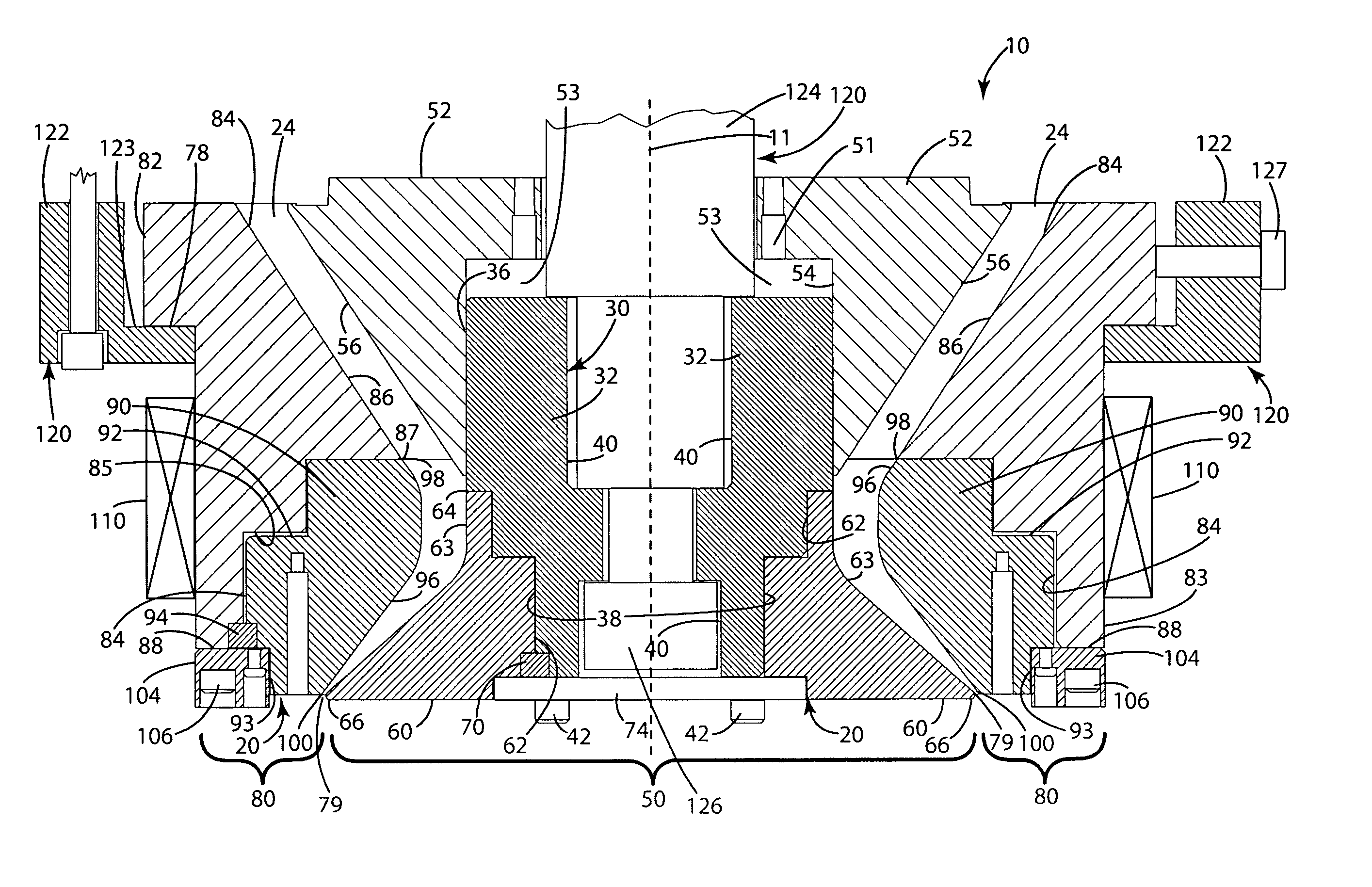
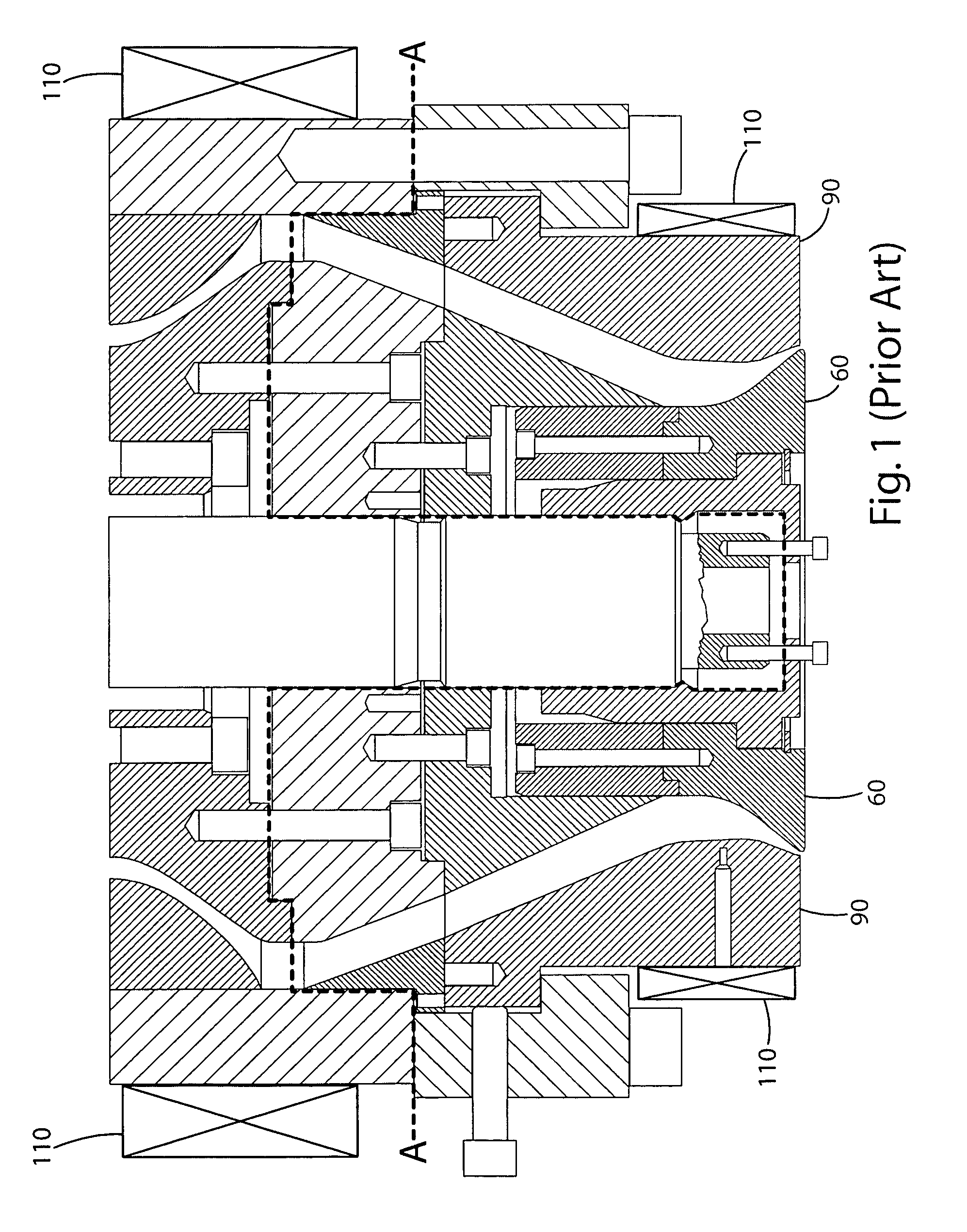
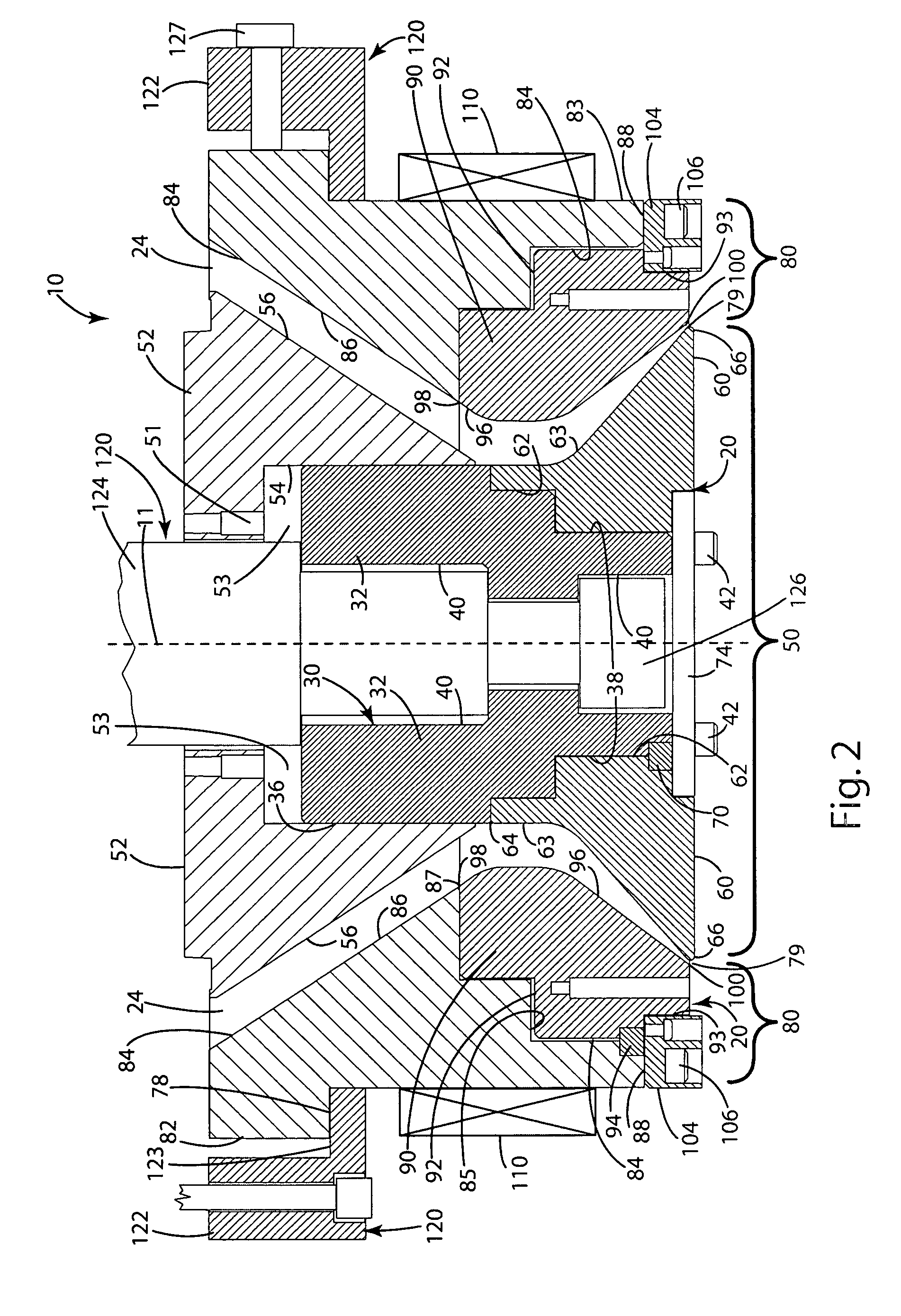
[0017] A die assembly 10 for a blow molding machine (not shown) constructed in accordance with the present invention is illustrated in FIG. 2. In general, the die assembly 10 includes a removable tool head 20 having an inner assembly 50 and an outer assembly 80 aligned along an axis 11 and defining a gap 79 therebetween. Heater coils 110 surround the die assembly 10 to heat the die assembly 10 to operational temperature so that the material in the die assembly 10 is heated until it is molten and forms a parisan that is extruded from the gap 79 between the inner and outer assemblies 50, 80. A support assembly 120 (partially illustrated in FIGS. 1 and 2) secures the die assembly 10 including the head tooling 20 to a blow molding machine (not shown).

[0018] The support assembly generally includes a die assembly retaining ring 122 and a die rod 124. The die assembly retaining ring 122 supports the outer assembly 80 (FIG. 2) to the blow molding machine. The die rod 124 supports the inner...


PUM

PropertyMeasurementUnit
timeaaaaaaaaaa
shapeaaaaaaaaaa
sizeaaaaaaaaaa

Abstract

A blow molding machine having a tool head that is quickly and efficiently interchanged to minimize the time required to switch between products being blow molded. The tool head is changed without the need for removing the heater bands and with minimal need for alignment during installation.

Description

BACKGROUND OF THE INVENTION [0001] The present invention is directed to a die assembly for a blow molding machine and, more specifically, to a die assembly having a tool head that is quickly and efficiently interchanged to minimize the time required to switch between products being blow molded. [0002] Blow molding machines are generally used to make thermoplastic containers and parts, such as fuel tanks for vehicles. In operation, blow molding machines typically extrude an elongated parisan between an inner ring and an outer ring on the tool head. To form a container, such as a vehicle fuel tank, a large die is clamped around the parisan while the extruded parisan is still partially molten. The parisan is then injected with air or an inert gas causing the parisan to expand and conform to the shape of the die. The shape, configuration, size, and relative arrangement of the inner and outer rings set the wall thickness, diameter, and shape of the extruded parisan. The shape, wall thick...

Claims


Application Information

Patent Timeline
Patent Type & Authority Applications(United States)
IPC IPC(8): B29C49/00B29C48/09
CPCB29C47/0023B29C47/0818B29C47/22B29C49/04B29C48/09B29C48/256B29C48/325
Inventor ARRUDA, ANTHONY C.DRAKE, DONALDHARRIS, MARK A.KNAGGS, RICHARD A.KOLLER, DAVID R.
Owner VISTEON GLOBAL TECH INC
Why Eureka
Try Eureka