Polymer nano-particle with polar core and method for manufacturing same

a technology of polar core and polymer nano-particles, applied in the field of nano-particles, can solve the problems of poor nano-particle formation, negative impact, and notoriously difficult preparation of some polymer nano-particles, and achieve the effect of improving the quality of nano-particles

Inactive Publication Date: 2006-08-03
BRIDGESTONE CORP
View PDF99 Cites 41 Cited by
  • Summary
  • Abstract
  • Description
  • Claims
  • Application Information

AI Technical Summary

Problems solved by technology

However, preparation of some polymer nano-particles, e.g., those with a polarized core, is notoriously difficult.
For example, even at −78° C., anionic polym

Method used


Image

  • Polymer nano-particle with polar core and method for manufacturing same
  • Polymer nano-particle with polar core and method for manufacturing same
  • Polymer nano-particle with polar core and method for manufacturing same

Examples


example 1

[0058] A 2-gallon reactor was used for preparation of polybutadiene. 5.30 lbs of hexane was charged into the reactor and the reactor was vented. 4.57 lbs butadiene / hexane blend (21.8 wt % butadiene)was charged into the reactor. The temperature of the mixture was set to 122 F. When the temperature stabilized (all of the thermal sensors in the reactor reached a constant value) at 122 F, 0.45 ml OOPS (1.6M) solution was charged into the reactor. Subsequently, 5.4 ml BuLi (1.64M) solution was charged into the reactor. The reaction then proceeded for 5 hours until 100% conversion.

[0059] The resultant product was anionic living. A portion of the living polymer was terminated by adding isopropanol to the reactor. After termination with isopropanol, the GPC analysis, using PS as the standard, showed the molecular weight of the polybutadiene: Mn=53800, Mw=58420, Mp=58380, and Mw / Mn=1.085.

example 2

[0060] 300 ml of the living polybutadiene (made in Example 1) was charged into a dry 1.5 L vessel. The vessel was then placed in a dry ice bath. After two hours of cooling, the temperature of the reaction mixture was −78° C. 20 ml of 2-VP was added to the content of the vessel. After one-hour reaction, 10 ml of DVB was added to the vessel. The vessel was then allowed to slowly warm up to room temperature of 23° C. After 1.5 hour reaction, the solution in the vessel turned into a red jelly-like material. The material in the vessel was then terminated with 0.5 ml isopropanol. The material was then taken out and dried under vacuum. GPC analysis showed that the resultant material contains about 50% of micellar particles. The impurity came from the unreacted polybutadiene. The material was dissolved in THF. The particles can be precipitated out using Hexane. H-NMR analysis showed that the particles contained 80% of 2-VP by weight.

examples 3 , 4 and 5

Examples 3, 4 and 5

[0061] For examples 3, 4, and 5, the same procedure as described in Example 2 was used, and the amounts of reactants used are listed in the following table:

Example 2Example 3Example 4Example 5BD solution used300 ml 300 ml 300 ml 300 ml 2-VP20 ml25 ml30 ml35 mlDVB10 ml12 ml15 ml20 mlProductMn289200287700356990409220Mw424840404160572590695430Mp410470429390682450739792Mw / Mn1.471.401.601.70

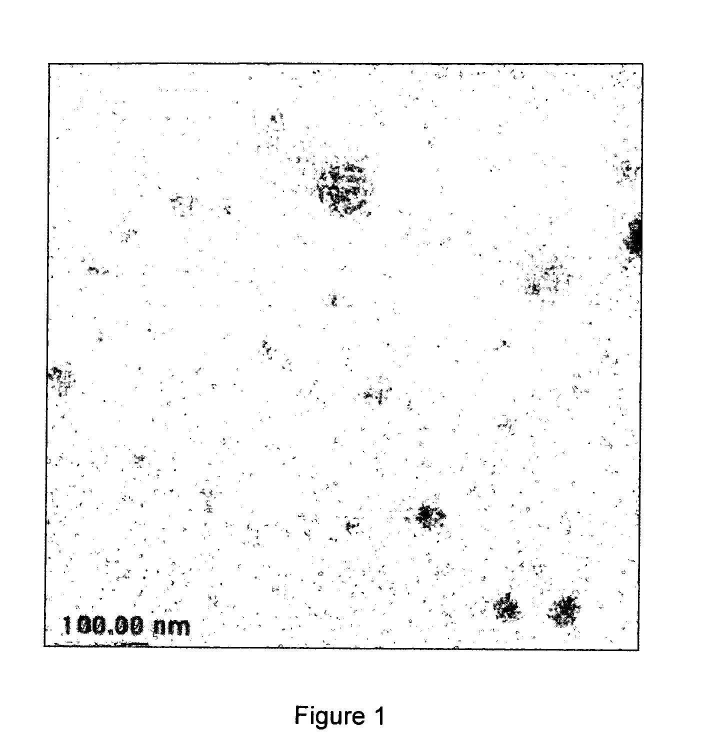
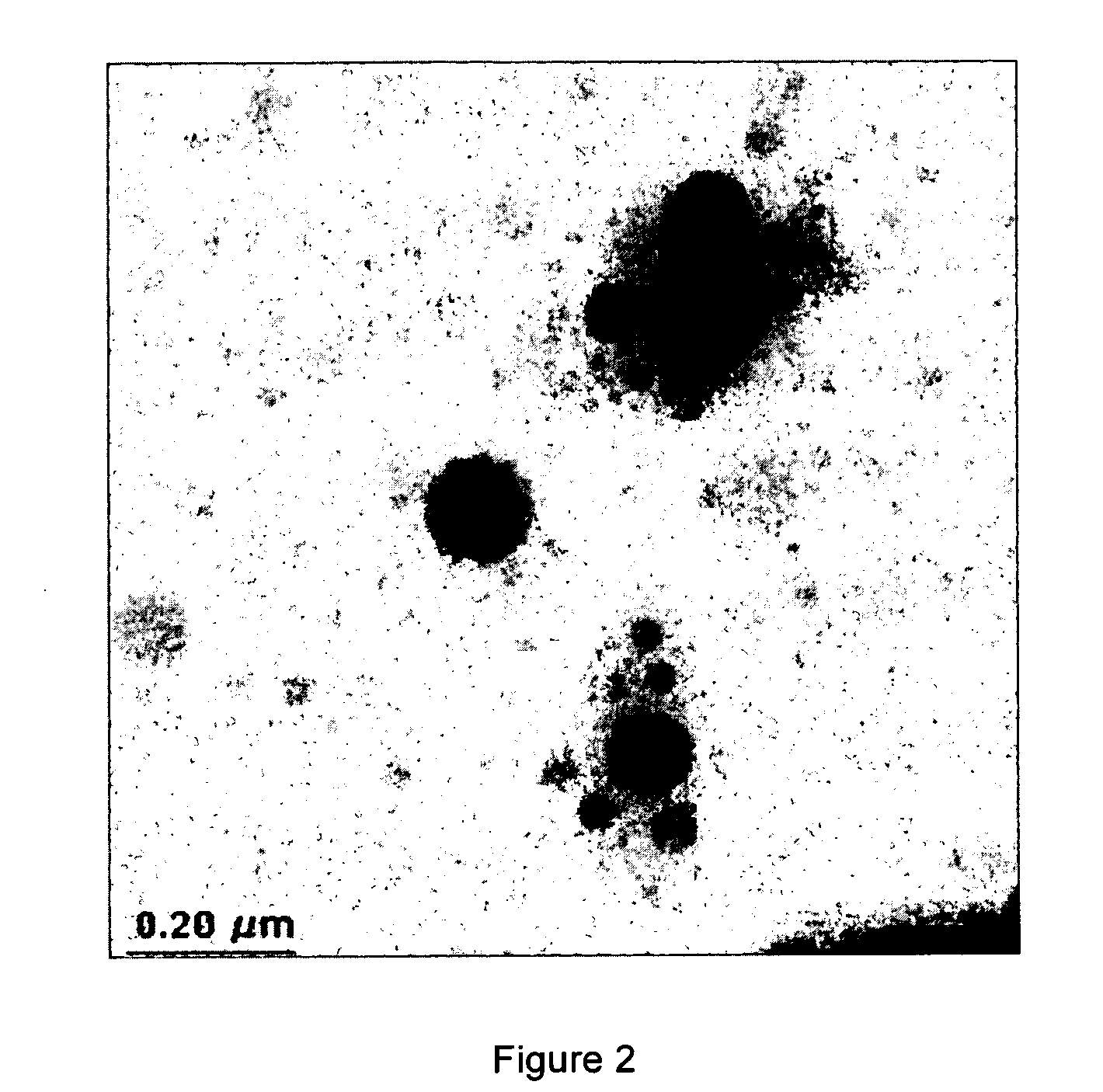
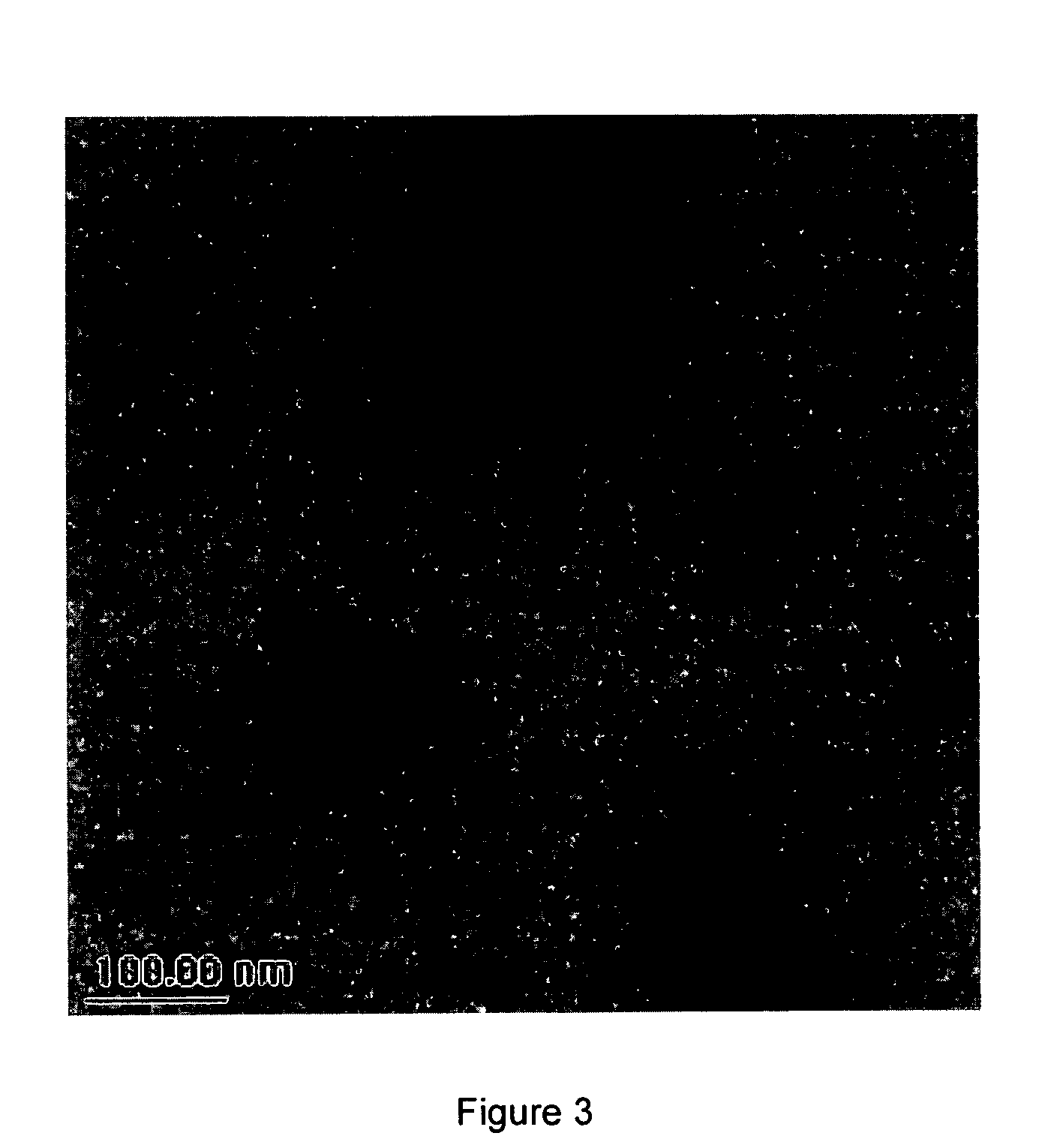
[0062]FIG. 1 presents an overall view of a particular sample of Example 2. FIGS. 2 and 3 show some details in the TEM pictures of the sample of Example 2. The distribution of size of the particles was broad, ranging from 120 to 5 nm.


PUM

PropertyMeasurementUnit
Temperatureaaaaaaaaaa
Fractionaaaaaaaaaa
Fractionaaaaaaaaaa

Abstract

The present invention provides a nano-particle comprising a shell and a polar core, their preparation, and their applications in ER fluids, polymeric product, rubber composition, tire product, hard disk drive gasket, matrix composition, and engine mount etc. The shell comprises a polymer formed from formula (I) monomers and the core comprises a polymer formed from formula (II) monomers, in which R1 and R2 are hydrogen; R3, R4, R5, R6, and up to three of R7, R8, R9, and R10 are each independently selected from the group consisting of hydrogen, methyl, ethyl, propyl, and isopropyl; and at least one of R7, R8, R9, and R10 is a polar group that is more polar than any one of R1, R2, R3, R4, R5, and R6 groups.

Description

BACKGROUND OF THE INVENTION [0001] The present invention is related to nano-particles comprising a shell and a relatively polar core, their preparation, and their industrial applications. More particularly, the shell of the nano-particle comprises a polymer formed from conjugated diene monomers, while the core comprises a polymer formed from vinyl monomers substituted by at least a polar group. [0002] Electrorheological (ER) fluids, alternatively known as electroviscous fluids, electroresponsive fluids, electrorestrictive fluids or jammy fluids, are colloidal dispersions of polymeric particles in a low conductivity continuous medium. When exposed to an external electric field, ER fluids show pronounced changes in flow properties, i.e., from liquid-like to solid-like, with typical response times in the order of milliseconds. This change is reversible as the liquid-like state returns upon removal of the electric field. This capability of ER fluids allows a variety of mechanical system...

Claims


Application Information

Patent Timeline
IPC IPC(8): C08L51/08
CPCC08F297/02C08F297/04
Inventor WANG, XIAORONGFOLTZ, VICTOR J.BRUMBAUGH, DENNIS R.
Owner BRIDGESTONE CORP
Why Eureka
Try Eureka