Method and apparatus for device detection and multi-mode security in a control network

a control network and multi-mode technology, applied in the field of device networking, can solve problems such as inconvenience, remote control might not be compatible with a videocassette recorder remote control, and separate and incompatible user interfaces and controls, and achieve the effect of facilitating encryption key exchang

Active Publication Date: 2006-08-03
SNAP ONE LLC
View PDF6 Cites 132 Cited by
  • Summary
  • Abstract
  • Description
  • Claims
  • Application Information

AI Technical Summary

Benefits of technology

[0014] The invention provides a method and apparatus for device discovery and multi-mode security in a wired and/or wireless control network. In one or more embodiments of the invention, a controlled device is configured with a system-level set of instructions and an application level set of instructions. The system level instructions may provide support for basic communications between the controlled device and the controller, e.g., for purposes of device discovery and identification. The application level instructions may provide support for the communication of application level messages between the controller and the controlled device, e.g., to access particular appliance control functions implemented by the given controlled device.
[0015] One or more embodiments of the invention implement a device discovery protocol in which the controlled device transmits an identifier of a preferred device driver to the controller, e.g., in response to a discovery request broadcast from the controller or as part of an announcement message when the controlled device is activated (e.g., turned “on”). The controller may use the device driver identifier to load an appropriate device driver for supporting application-level communications with the controlled device.
[0016] In one or more embodiments of the invention, the controlled device is equipped with a user-configurable parameter for selecting between multiple security modes. For example, in one or more security modes, the controlled device may require that encrypted communications be establ

Problems solved by technology

However, most of this equipment has been developed separately and has separate and incompatible user interfaces and controls.
There are many examples of inconveniences caused by separate and incompatible user interfaces.
A television set may be equipped with a remote control, but that remote control might not be compatible with a remote control for a videocassette recorder.
Thus, much effort is required to control devices having separate and incompatible user interfaces.
However, such a remote control does not control lights; heating, ventilation, and air conditioning equipment (HVAC), telephone lines, relay-controlled devices, devices with electrical serial data ports, or other devices.
Moreover, such a remote control is not responsive to input from other devices, for example, devices emitting infrared signals.
Thus, infrared remote controls are ineffective for home automation.
Since the X-10 system relies on a power line carrier, the performance of an X-10 system may be degraded by power line noise.
Attenuation of power line carrier signals on a power line network is variable and often unpredictable, affecting the reliability of power line carrier transmission.
Other power line carrier transmission techniques may interfere with X-10 signals.
Because of the limited carrier frequency, the data transmission rates are slow, limiting use to situations where response time is not critical and where high data throughput is not important.
Some X-10 devices have problems with data collisions during simultaneous transmissions.
Thus, the X-10 system is of limited utility for home automation.
One of the problem

Method used


Image

  • Method and apparatus for device detection and multi-mode security in a control network
  • Method and apparatus for device detection and multi-mode security in a control network
  • Method and apparatus for device detection and multi-mode security in a control network

Examples


Embodiment Construction

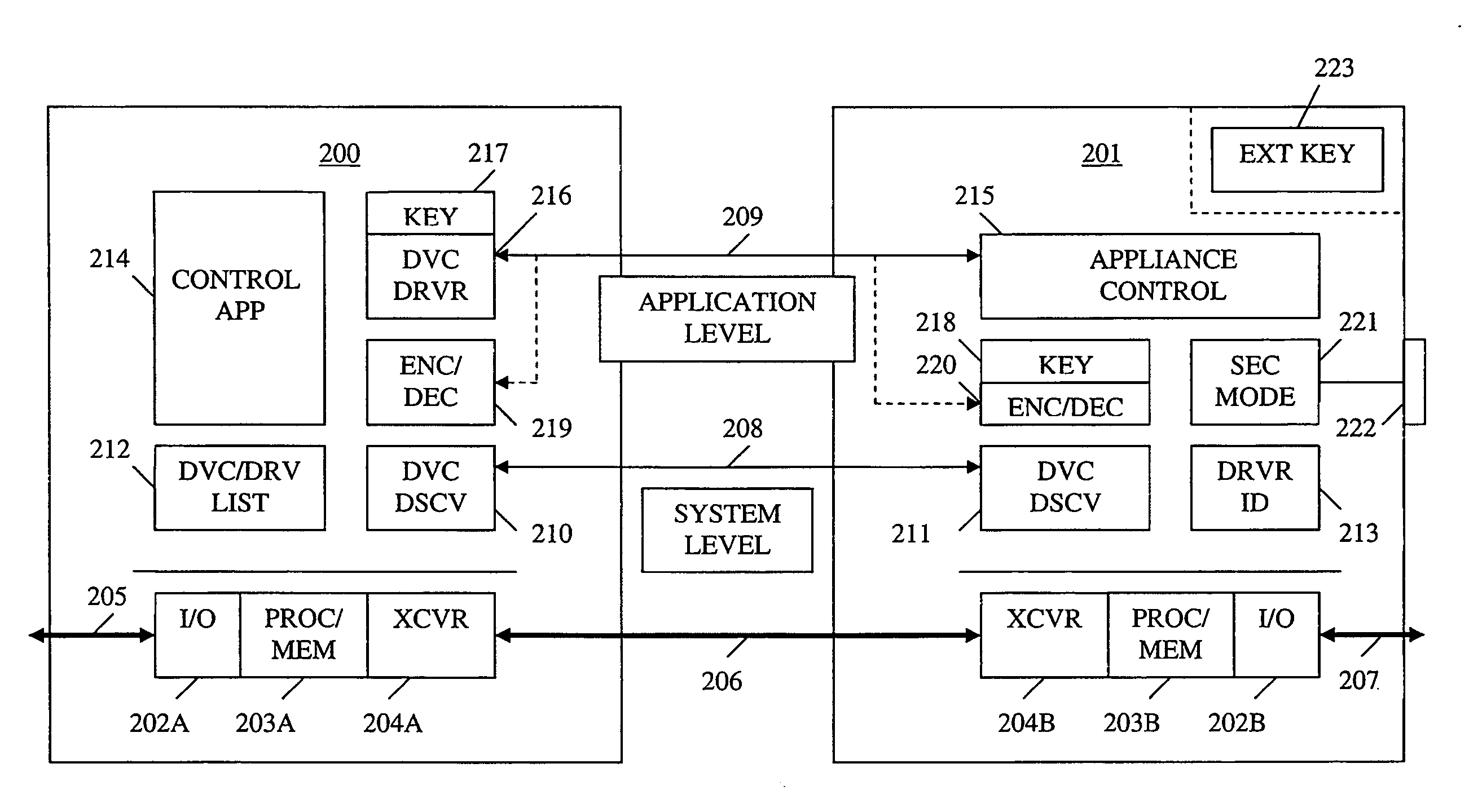
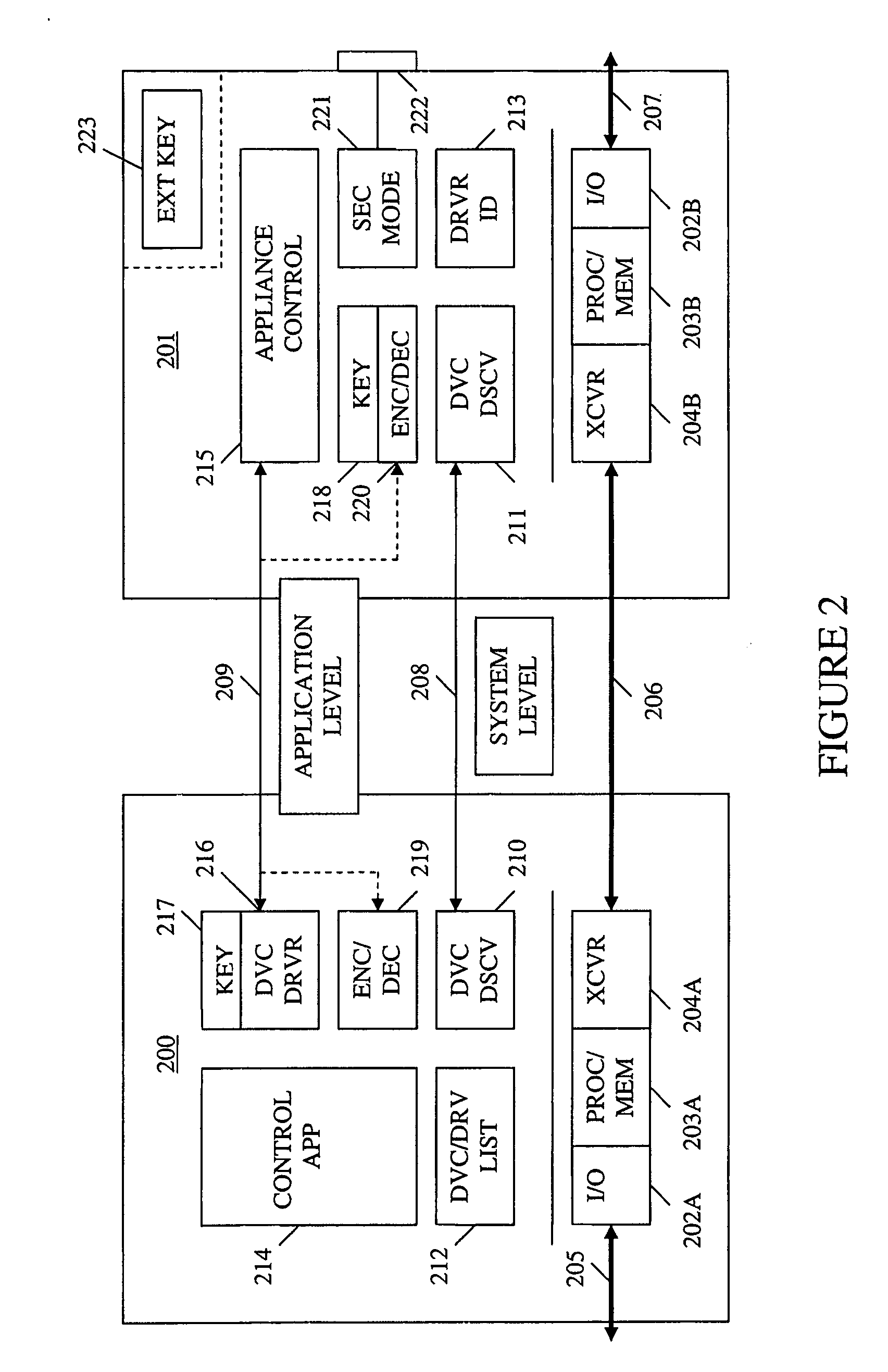
[0028] The present invention provides device detection and multi-mode security for a wired and / or wireless control network. In the following description, numerous specific details are set forth to provide a more thorough description of the invention. It will be apparent, however, to one skilled in the art, that the invention may be practiced without these specific details. In other instances, well known features have not been described in detail so as not to obscure the invention.

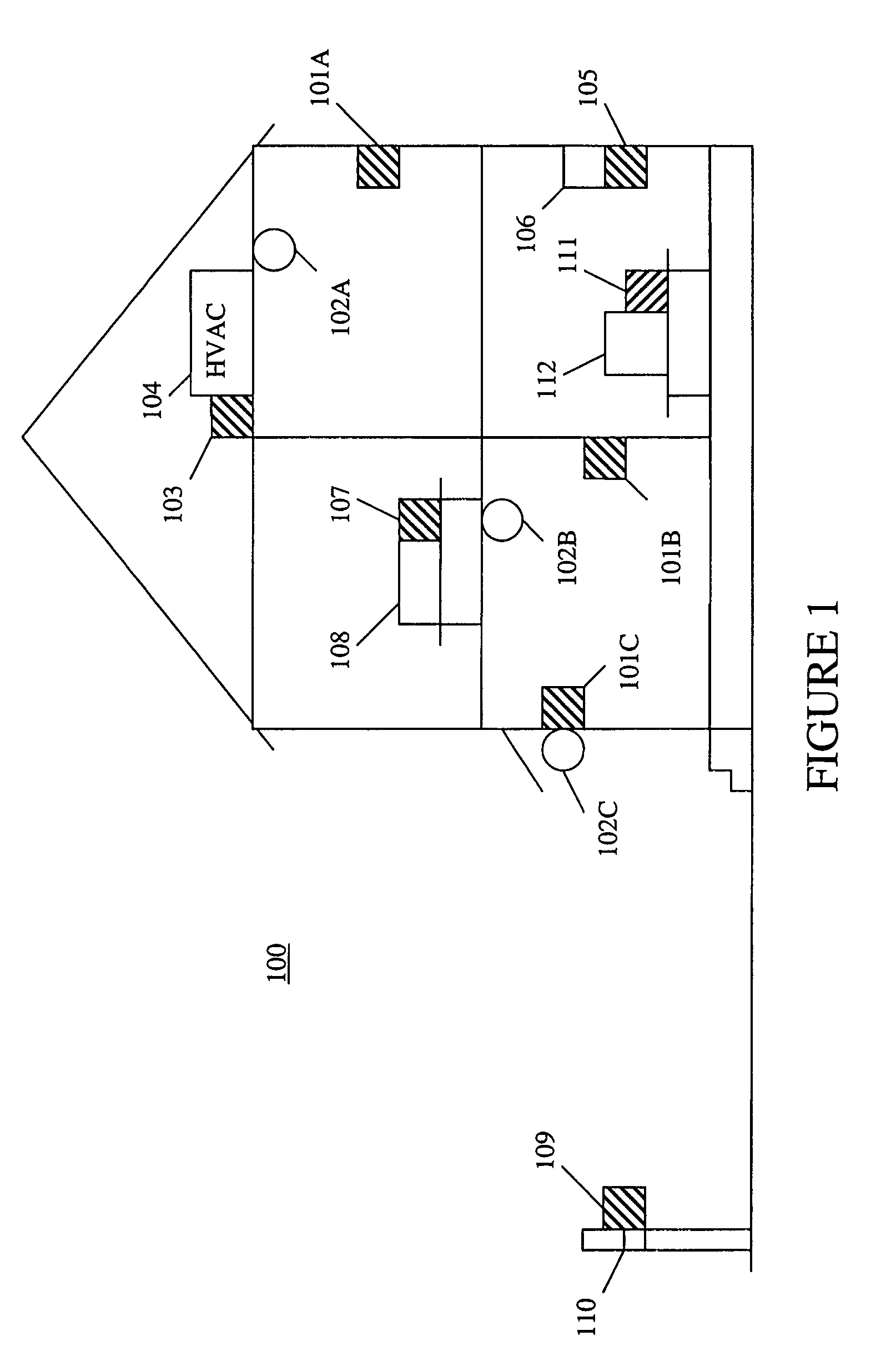
[0029] In the preferred embodiment of the present invention, the control network is implemented as a wireless network, for example, using transmission frequencies that will pass through the structure of the common home without undue attenuation, and using a signal strength that localizes the transmission to the immediate vicinity of the home. The present invention also contemplates the use of such a control network in any other environment where centralized control of appliances is desired, such as in a bu...


PUM


Abstract

A method and apparatus for device discovery and multi-mode security in a wired and/or wireless control network are described. A controlled device is configured with discovery-level instructions and application-level control instructions. The controlled device includes a user-configurable parameter for selecting between multiple security modes. In one or more security modes, the controlled device may ignore application-level messages until encrypted communications are established with a controller. In one mode, the encrypted communication is established with an encryption key exchange using a predetermined security key. In another mode, a specific key is manually entered into the controller by the user/administrator to facilitate the encryption key exchange. Additionally, for control applications where security is not important, an unencrypted security mode may be implemented. A driver ID provided by the controlled device facilitates loading of a preferred device driver by the controller.

Description

FIELD OF THE INVENTION [0001] The invention relates to the field of device networking, and more specifically, to device detection and security in a wired and / or wireless control network. [0002] A portion of the disclosure of this patent document contains material which is subject to copyright protection. The copyright owner has no objection to the facsimile reproduction by anyone of the patent document or the patent disclosure, as it appears in the Patent and Trademark Office file or records, but otherwise reserves all copyrights associated with this document. BACKGROUND [0003] A modern home includes many appliances and devices intended to provide comfort and convenience to the residents. For example, a home may include lighting equipment; security equipment; entertainment equipment; and heating, ventilation, and cooling (HVAC) equipment. However, most of this equipment has been developed separately and has separate and incompatible user interfaces and controls. To set the equipment...

Claims


Application Information

Patent Timeline
IPC IPC(8): H04L9/00
CPCH04L12/2803H04L12/2809H04L12/281H04L63/0428H04L63/061H04L2012/2841H04L2012/285H04W12/02H04W12/04H04W12/03H04W12/041H04W12/0471
Inventor SMITH, ERICGIST, JAMES
Owner SNAP ONE LLC
Why Eureka
Try Eureka