Viewer for test apparatus hardware

a technology for test apparatus and viewer, applied in the field of graphical user interface (gui) tools, can solve the problems of inability to remotely view, otherwise very inconvenient or inefficient, etc., and achieve the effect of simplifying the viewer development process and significantly reducing the development time and cost of the viewer

Inactive Publication Date: 2006-08-03
CREDENCE SYSTEMS
View PDF6 Cites 13 Cited by
  • Summary
  • Abstract
  • Description
  • Claims
  • Application Information

AI Technical Summary

Benefits of technology

[0007] The present invention provides a common viewer framework that simplifies the viewer development process and significantly reduces the development time and cost of viewer development. Under this framework, viewers for different hardware devices are developed according to a common application programming interface (API) and operate as plug-ins to a common viewer tool. The API may be provided as part of a software development kit to the maker of the hardware device to be viewed, so that the task of developing viewers can be delegated to the individuals with special knowledge about the hardware devices.

Problems solved by technology

By contrast, in conventional viewer systems for a test apparatus, remote viewing is not possible, or otherwise very inconvenient or inefficient, if the viewer files have not been custom-developed and then stored and carried on the remote access device.

Method used


Image

  • Viewer for test apparatus hardware
  • Viewer for test apparatus hardware
  • Viewer for test apparatus hardware

Examples


Embodiment Construction

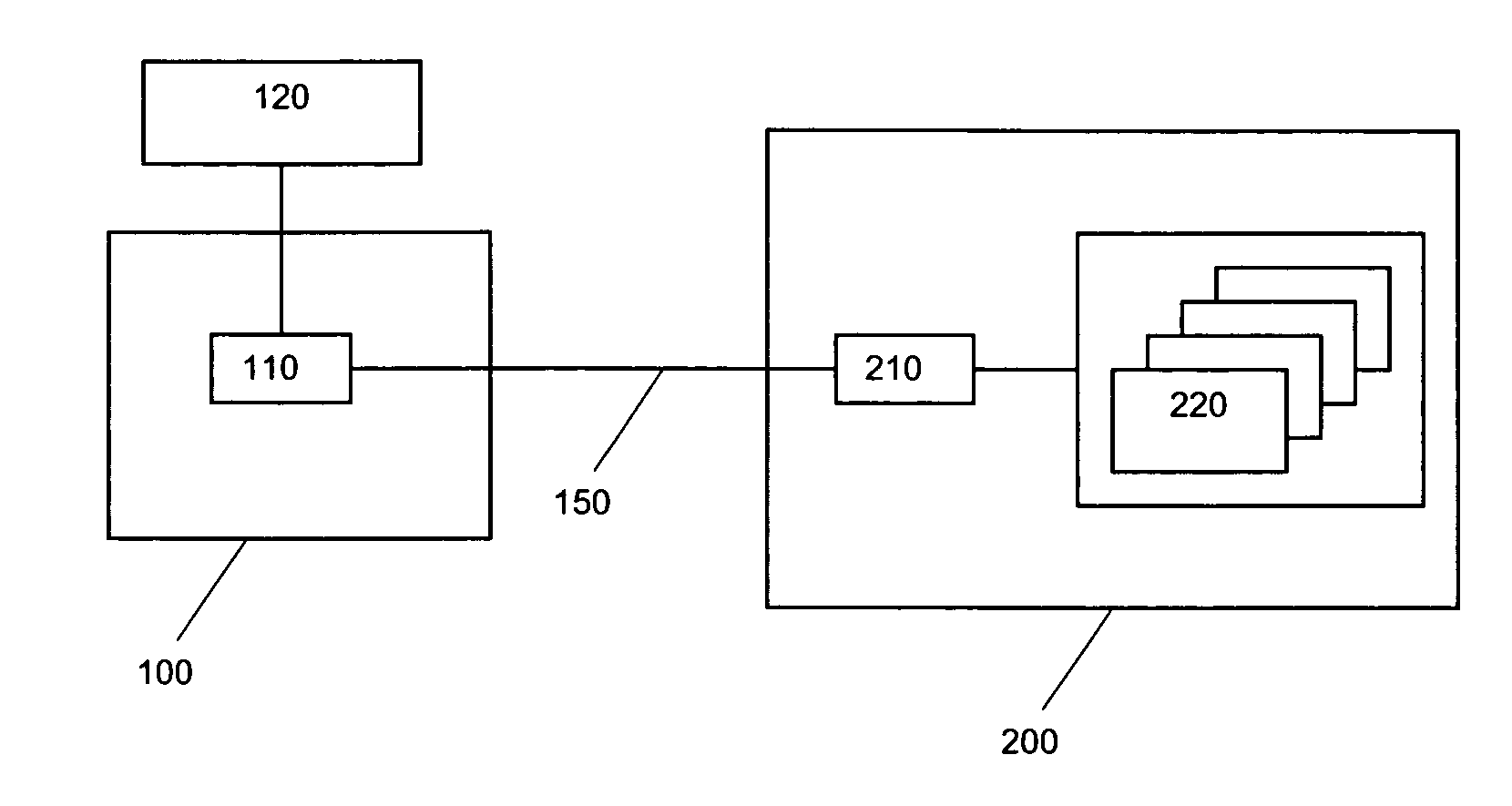
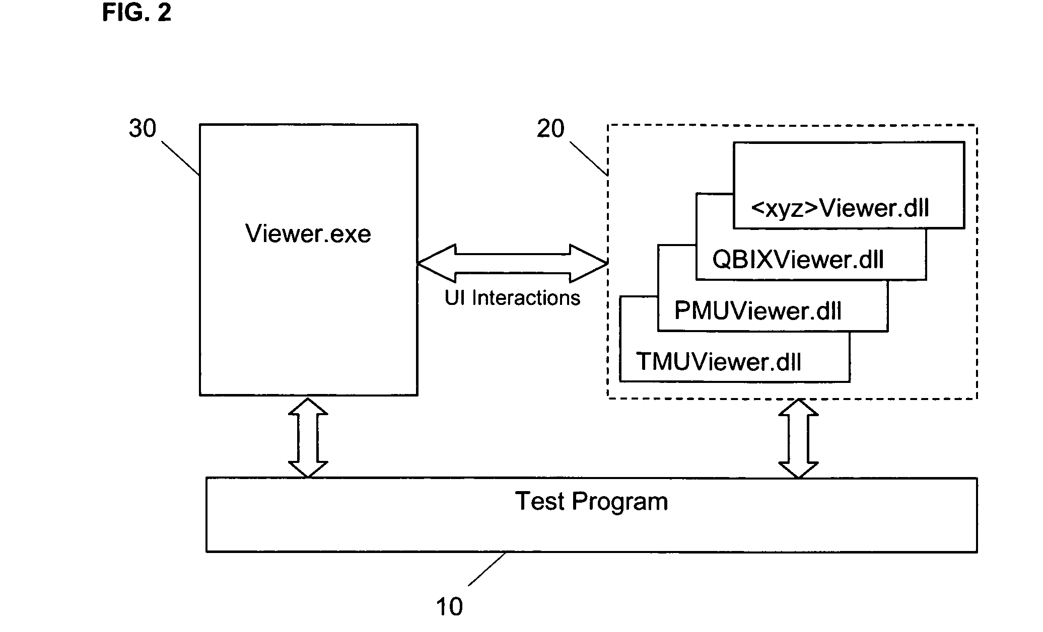
[0020]FIG. 2 provides a schematic illustration of the common viewer framework employed in various embodiments of the invention, and illustrate a test program 10, a plurality of viewers 20, and a viewer tool 30. The test program 10 represents the software that controls the components of a test apparatus to carry out a test. Each of the viewers 20 corresponds to a hardware module of the test apparatus and contains a representation of the circuit layout of the hardware module. All of them are developed based on an application programming interface (API) for the viewer tool 30 and are configured as plug-ins for the viewer tool 30. When a viewer is plugged into the viewer tool 30, the viewer tool 30 renders a GUI display in accordance with the contents of the viewer.

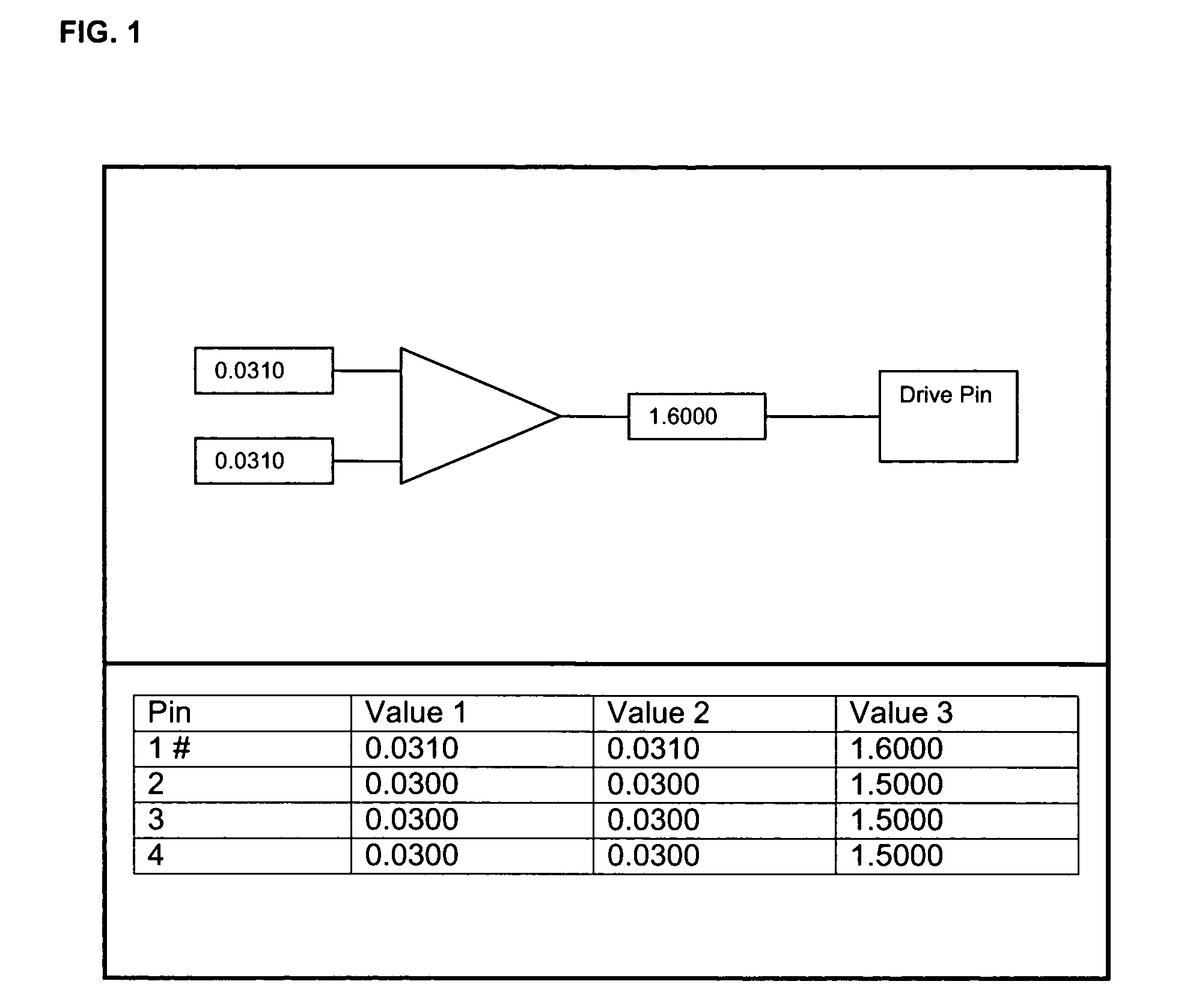
[0021] The GUI display or viewer typically includes a circuit layout, tabular listings of various parameters of the circuit and various user input (UI) controls. A sample illustration is provided in FIG. 3. The UI controls m...


PUM


Abstract

A common viewer framework simplifies the viewer development process and significantly reduces the development time and cost of viewer development. Based on this framework, viewers for different hardware devices are developed according to a common application programming interface (API) and operate as plug-ins to a common viewer tool. Also, the API may be provided as part of a software development kit (SDK) to the maker of the hardware device to be viewed, so that the task of developing viewers can be delegated to the individuals with special knowledge of the hardware devices.

Description

BACKGROUND OF THE INVENTION [0001] 1. Field of the Invention [0002] The present invention relates generally to electronic device testing, and more particularly, to graphical user interface (GUI) tools that are used to view the hardware components of a test apparatus. [0003] 2. Description of the Related Art [0004] GUI tools that are known as viewers display the circuit layout of hardware devices and provide interactive control of various parameters and circuit components of the hardware devices. In the field of electronic device testing, these viewers are used during the design and debugging of test programs. [0005]FIG. 1 provides a simplified illustration of a viewer display for a pin drive circuit of a test apparatus. The upper part of the display illustrates the components of the pin drive circuit associated with a selected pin (Pin 1) and voltage values measured at certain points in the circuit. The lower part of the display provides a tabular listing of the voltage values for p...

Claims


Application Information

Patent Timeline
Patent Type & Authority Applications(United States)
IPC IPC(8): G06F11/00
CPCG06F11/2294
Inventor SHARMA, YOGENDRA KUMAR
Owner CREDENCE SYSTEMS
Why Eureka
Try Eureka