Method and system for a target device display simulation

a target device and display simulation technology, applied in computing, instruments, electric digital data processing, etc., can solve the problems of difficult for a programmer to ensure that a particular chosen graphical user interface (gui) of the handheld will appear, the display and functionality of the target device is often not well reflected in the capabilities of the development system, and achieve the effect of simulated high resolution displays

Active Publication Date: 2006-08-03
MICROSOFT TECH LICENSING LLC
View PDF12 Cites 50 Cited by
  • Summary
  • Abstract
  • Description
  • Claims
  • Application Information

AI Technical Summary

Benefits of technology

[0011] An aspect of the invention includes a development system that can produce a real time view of a target digital device such that a developer can perceive what the actual device will look and feel like when operating the handheld device with a new application. In order to accomplish this, a development system displays an image form of the targeted handheld digital device and manipulates the development system display of the handheld device to indicate text sized proportionally to the ...

Problems solved by technology

Programmers attempting to program complex software applications quickly find that traditional visual software development systems are unsuitable for programming applications to run on the myriad of devices available.
Specifically, given the multitude of variations of interfaces, screen sizes, and resolutions among the handheld devices, it can be very difficult for a programmer to ensure that a particular chosen graphical user interface (GUI) of the handheld will appear and work correctly on multiple devices.
For example, the display and functionality of the target device is often not well reflected in the capabilities of the development system.
This can be time consuming and inefficient, especially if a programmer wishes to port the application to a wide variety of p...

Method used


Image

  • Method and system for a target device display simulation
  • Method and system for a target device display simulation
  • Method and system for a target device display simulation

Examples


Embodiment Construction

Overview

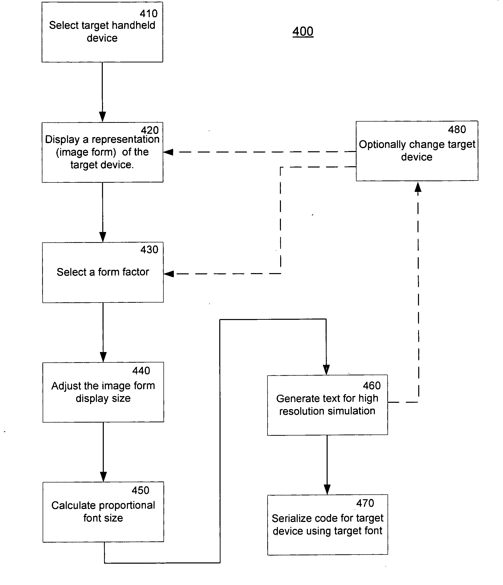
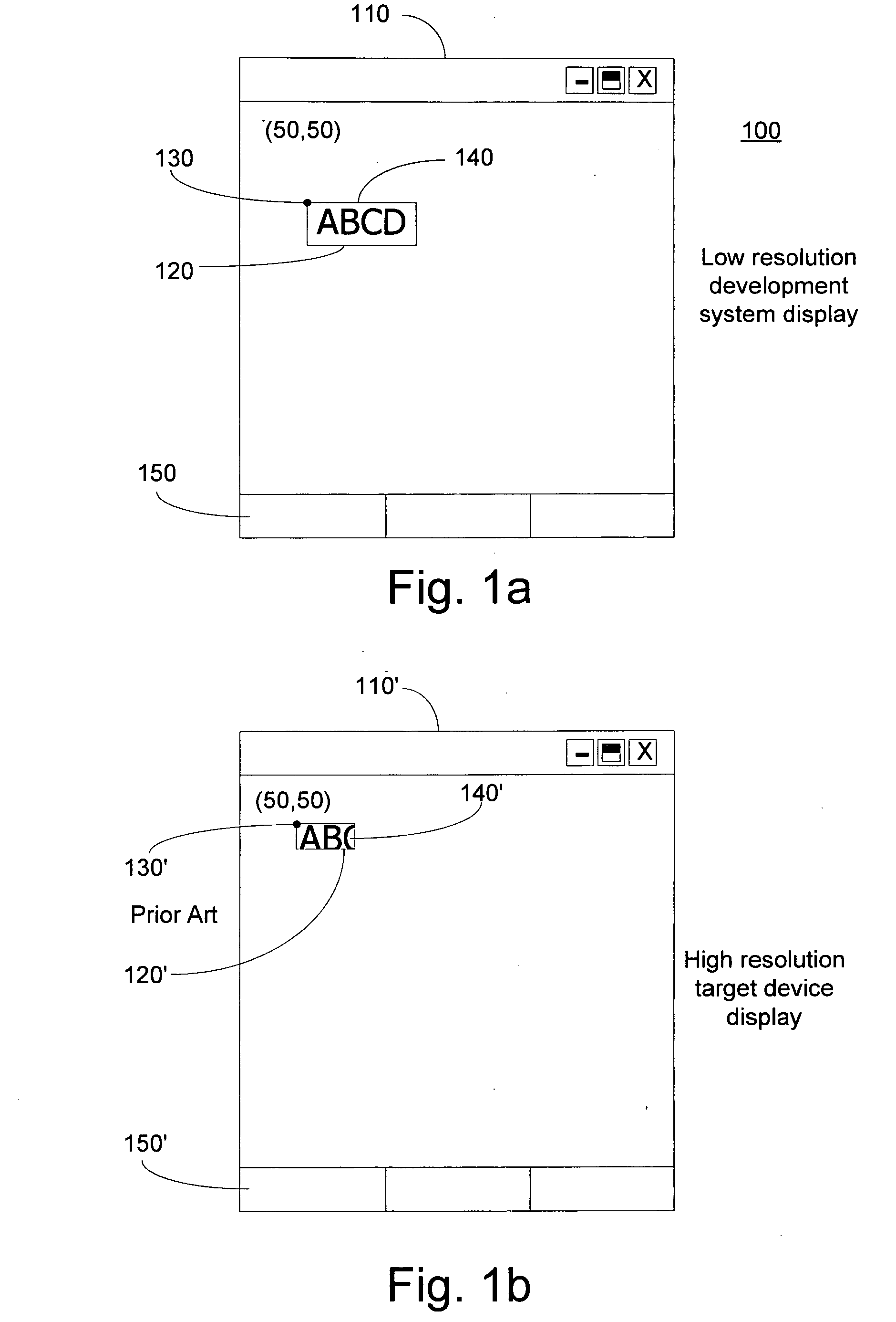
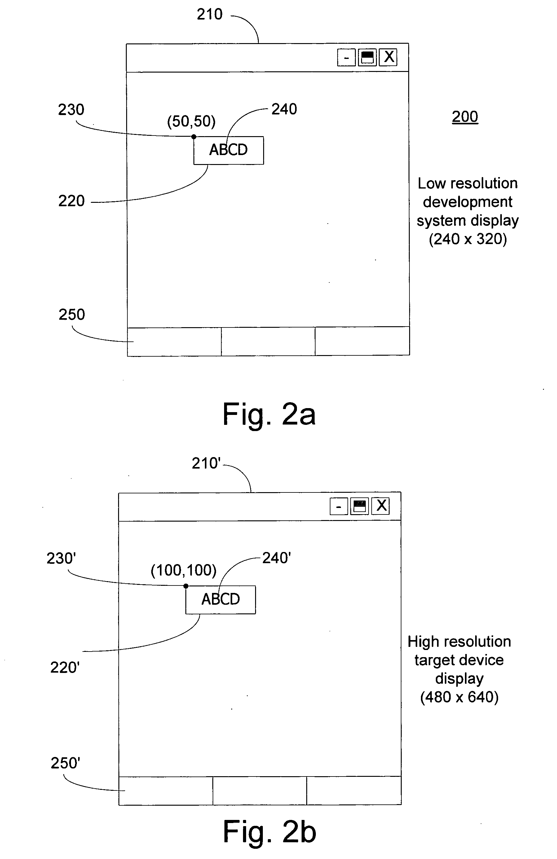
[0021] In one embodiment of the invention, a target digital device having a high resolution display is simulated a development system having a low resolution display. The invention may also be embodied in an application where the target digital device has a low resolution compared to the resolution of the display of the development system. The development system is used by handheld device developers for the generation of text and new applications for handheld digital devices. One advantage of the present invention is the ability of the user / developer to view the handheld device in a manner that depicts a high resolution aspect of the target device. This high resolution simulation using a low resolution display, or the reverse, allows the developer to immediately see how the target device will display the development text or application and thus saves both total development and debug time. Although examples of target digital devices included herein include handheld digital ...


PUM


Abstract

A method of viewing a high resolution display on a low resolution development system display for a digital device includes selecting a target device and identifying an image form for the selected device. An image form displays a realistic form of the selected target device. A form factor is selected which represents the display capabilities of the target device. The image form size is adjusted such that the developer may see text in proper proportion to the image form so as to simulate the look of the high resolution display of the target device. Object code for the target device is generated which contains the proper font size to correspond to the image form and font on the development display.

Description

CROSS REFERENCE TO RELATED APPLICATIONS [0001] This application shares some subject matter with co-owned U.S. patent application Ser. No. 10 / 922,580, filed Aug. 20, 2004, entitled “Form Skin And Design Time WYSIWYG For .Net Compact Framework” and is incorporated herein by reference in its entirety.FIELD OF THE INVENTION [0002] The invention relates to the field of computer programming. More specifically, the invention relates to visual programming environments for creating software designed to run on target digital devices. BACKGROUND OF THE INVENTION [0003] An increasing number of portable computer devices are available in the market. These devices include handheld or pocket sized computers, phones and personal digital assistants of various form factors and capabilities. As the computing power and memory capabilities of the handheld devices increase, users are demanding access to more powerful software applications. [0004] Programmers attempting to program complex software applicat...

Claims


Application Information

Patent Timeline
IPC IPC(8): G09G5/02
CPCG06F8/38H04N7/01
Inventor YAN, XINAMOS, KEIRA
Owner MICROSOFT TECH LICENSING LLC
Why Eureka
Try Eureka