
System for limiting pressure in a fine filter chamber for a dishwasher

a filter chamber and dishwasher technology, applied in the field of dishwashers, can solve the problems of reducing the overall efficiency of the filtering process, reducing the overall efficiency of the washing operation, etc., and achieve the effects of reducing the pressure of the washing fluid, efficient filter operation, and efficient cleaning

Inactive Publication Date: 2006-08-10
MAYTAG
View PDF42 Cites 33 Cited by
  • Summary
  • Abstract
  • Description
  • Claims
  • Application Information

AI Technical Summary

Benefits of technology

[0009] In accordance with the most preferred embodiment of the invention, in addition to the venturi, a bleed port is located proximate to the inlet of the filter chamber. The location and size of the bleed port serves to further reduce the pressure of the washing fluid entering the filter chamber. With this arrangement, the pressure of the washing fluid entering the filter chamber can remain low for efficient filter operation while, at the same time, the velocity of the washing fluid that is supplied to the wash arms is held high for efficient cleaning purposes.

Problems solved by technology

Unfortunately, supplying the filter at high pressure will often reduce the overall efficiency of the filtering process.
When operating at high pressure, the filter becomes clogged quickly, causing food soils to be released back into the wash system to circulate with the washing fluid.
Without proper filtration, the level of food soils circulating in the washing fluid will rise, resulting in a decrease in the overall efficiency of the washing operation.

Method used


Image

  • System for limiting pressure in a fine filter chamber for a dishwasher
  • System for limiting pressure in a fine filter chamber for a dishwasher
  • System for limiting pressure in a fine filter chamber for a dishwasher

Examples


Embodiment Construction

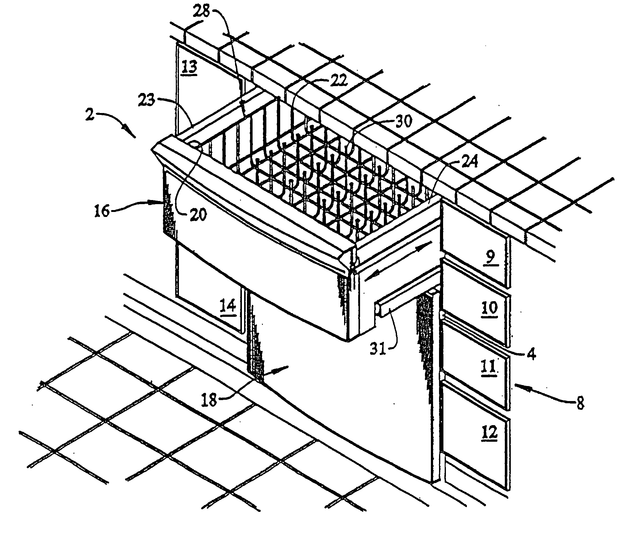
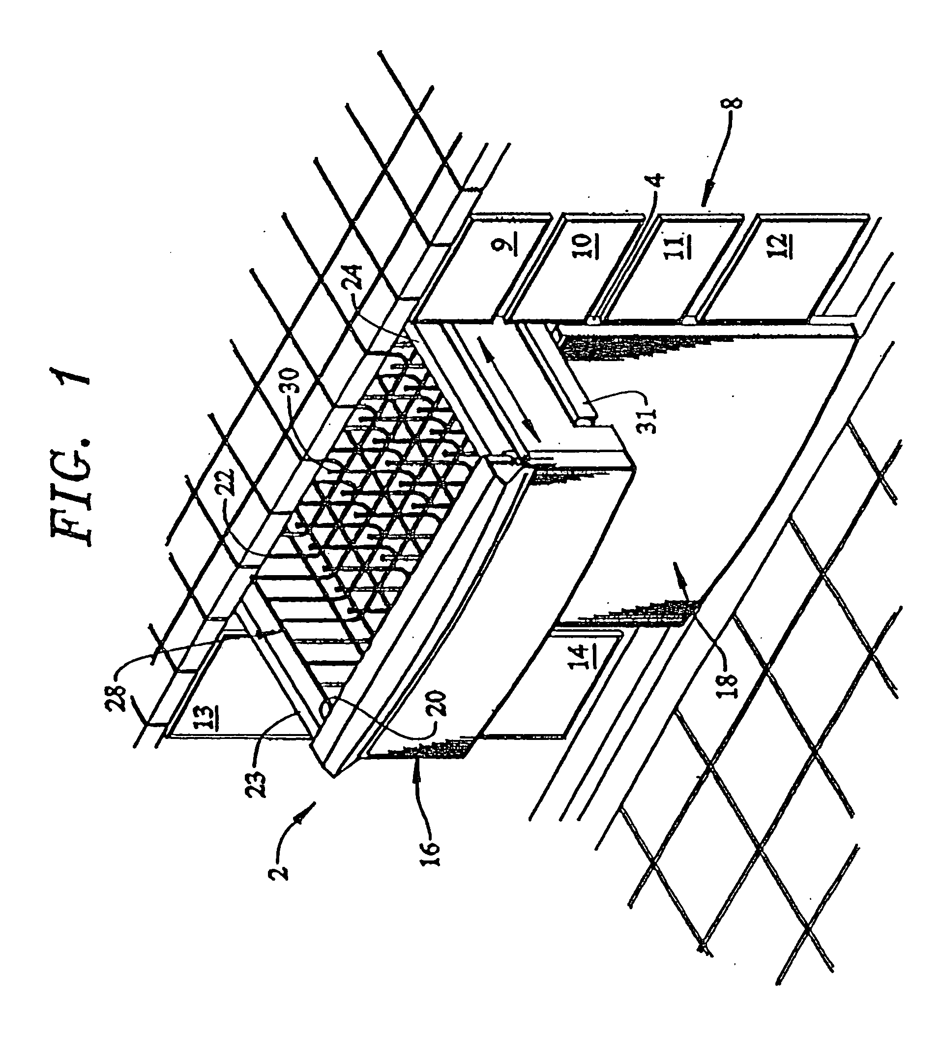
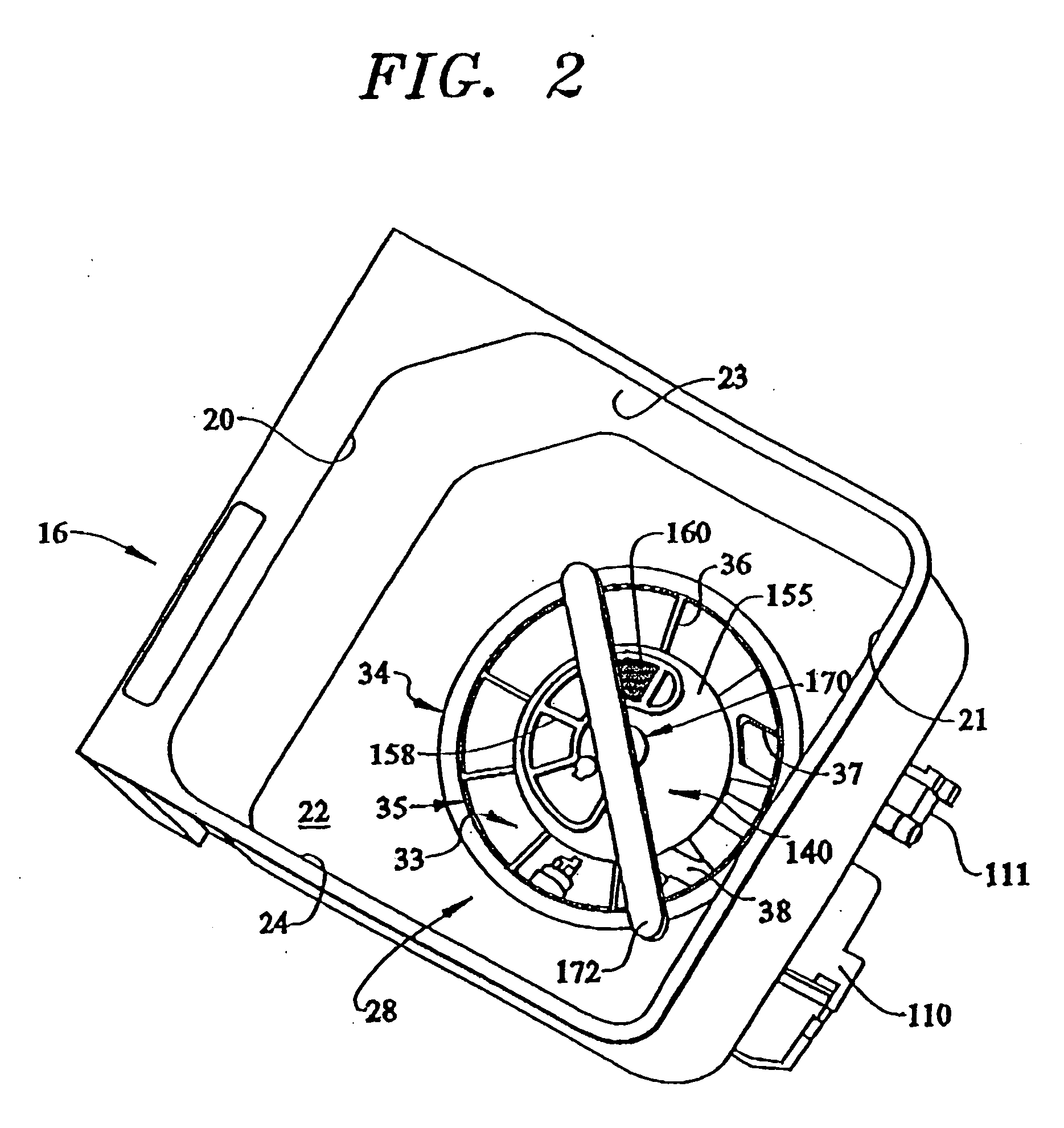
[0020] With initial reference to FIGS. 1 and 2, a dishwasher constructed in accordance with the present invention is generally indicated at 2. As shown, dishwasher 2 includes a support frame 4 arranged below a kitchen countertop 6. Also below kitchen countertop 6 is shown cabinetry 8 including a plurality of drawers 9-12, as well as cabinet doors 13 and 14. Although the actual dishwasher into which the present invention may be incorporated can vary, the invention is shown in connection with dishwasher 2 depicted as a dual cavity dishwasher having an upper drawer 16 and a lower drawer 18. As best illustrated in FIG. 1, upper drawer 16 takes the form of a slide-out drawer unit having a small or medium capacity so as to be used for cleaning glassware and the like, while lower drawer 18 is illustrated as a larger capacity drawer for washing items such as dinnerware, cookware and other large sized objects. Of course, upper and lower drawers 16 and 18 could also be similar in size.

[0021]...


PUM


Abstract

A dishwasher includes wash chamber, a wash system for supplying washing fluid to wash arms to clean articles arranged in the wash chamber, and a washing fluid manifold having an inlet portion, an outlet portion and a passage interconnecting the inlet and outlet portions. A filter chamber is fluidly connected to the washing fluid manifold for removing food soil from the washing fluid. A venturi is provided in the passage for establishing a low pressure region. A sampling port for feeding the filter chamber is located in the low pressure region. In addition, a bleed port is provide near an inlet of the filter chamber. In this manner, washing fluid enters the filter chamber at low pressure to increase the efficiency of a filtering process, while washing fluid enters the wash arms at a high velocity to efficiently perform a washing operation.

Description

BACKGROUND OF THE INVENTION [0001] 1. Field of the Invention [0002] The present invention pertains to the art of dishwashers and, more particularly, to a system for limiting pressure in a filter chamber in a dishwasher. [0003] 2. Discussion of the Prior Art [0004] A typical dishwasher includes a closed system where washing fluid is pumped from a sump into upper and lower wash arms such that kitchenware retained on vertically spaced racks within a tub of the dishwasher will be sprayed with the washing fluid for cleaning purposes. The washing fluid is heated, filtered and recirculated. Prior to recirculating the washing fluid, the fluid is directed through one or more filters to remove soil from the fluid, with the soil being collected in a chamber. Periodically, the system is purged in order to drain the collection chamber of the soil. [0005] In general, washing fluid is circulated in the system at a relatively high pressure in order to ensure an adequate fluid supply to the upper an...

Claims


Application Information

Patent Timeline
Patent Type & Authority Applications(United States)
IPC IPC(8): B08B7/04B08B3/00B08B9/20
CPCA47L15/0084A47L15/4204A47L15/4225A47L15/4227H02K7/116
Inventor HEDSTROM, KRISTEN K.PALM, MARK E.WELCH, RODNEY M.
Owner MAYTAG
Learn More