Shock absorber

a technology of shock absorber and shock absorber, which is applied in the direction of shock absorber, wound spring, transportation and packaging, etc., can solve the problems of affecting the smooth vertical movement of the piston, and causing the cylinder to twis

Inactive Publication Date: 2006-08-10
KYB CORP +1
View PDF7 Cites 5 Cited by
  • Summary
  • Abstract
  • Description
  • Claims
  • Application Information

AI Technical Summary

Benefits of technology

[0010] In this embodiment, the upper and lower salients, which are formed on the upper part and the lower part of the main body, respectively, prevent the suspension spring bearing from moving or vibrating with res

Problems solved by technology

However, when the same roll swages are applied to a shock absorber having a single cylinder, it may distort the cylinder and interfere with smooth vertical movement of a piston sidably inserted in the cylinder.
If the suspension spring bearing is fixed by welding instead of roll swaging, the welding may distort the cylinder, which may also interfere with smooth vertical movement of the piston.
In addition,

Method used


Image

  • Shock absorber
  • Shock absorber
  • Shock absorber

Examples


Embodiment Construction

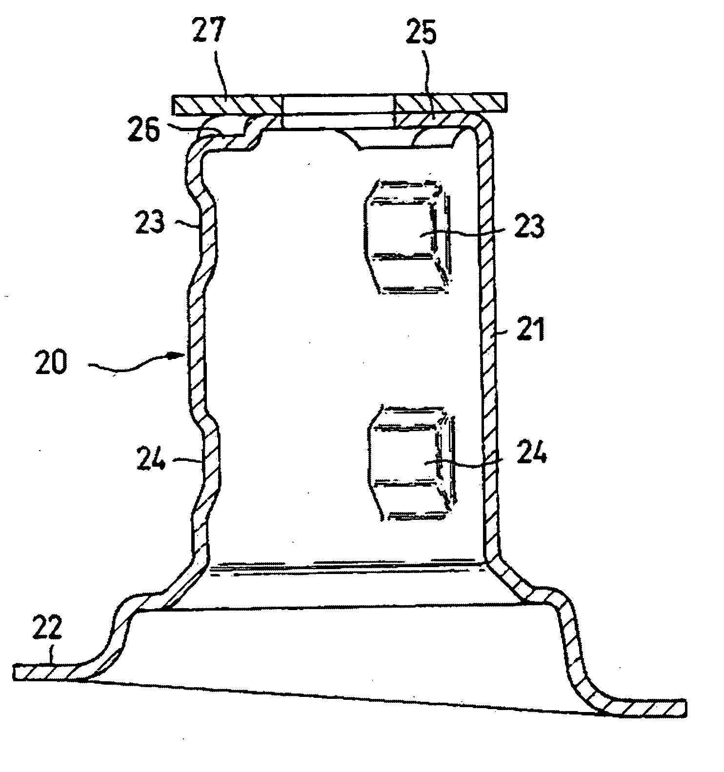
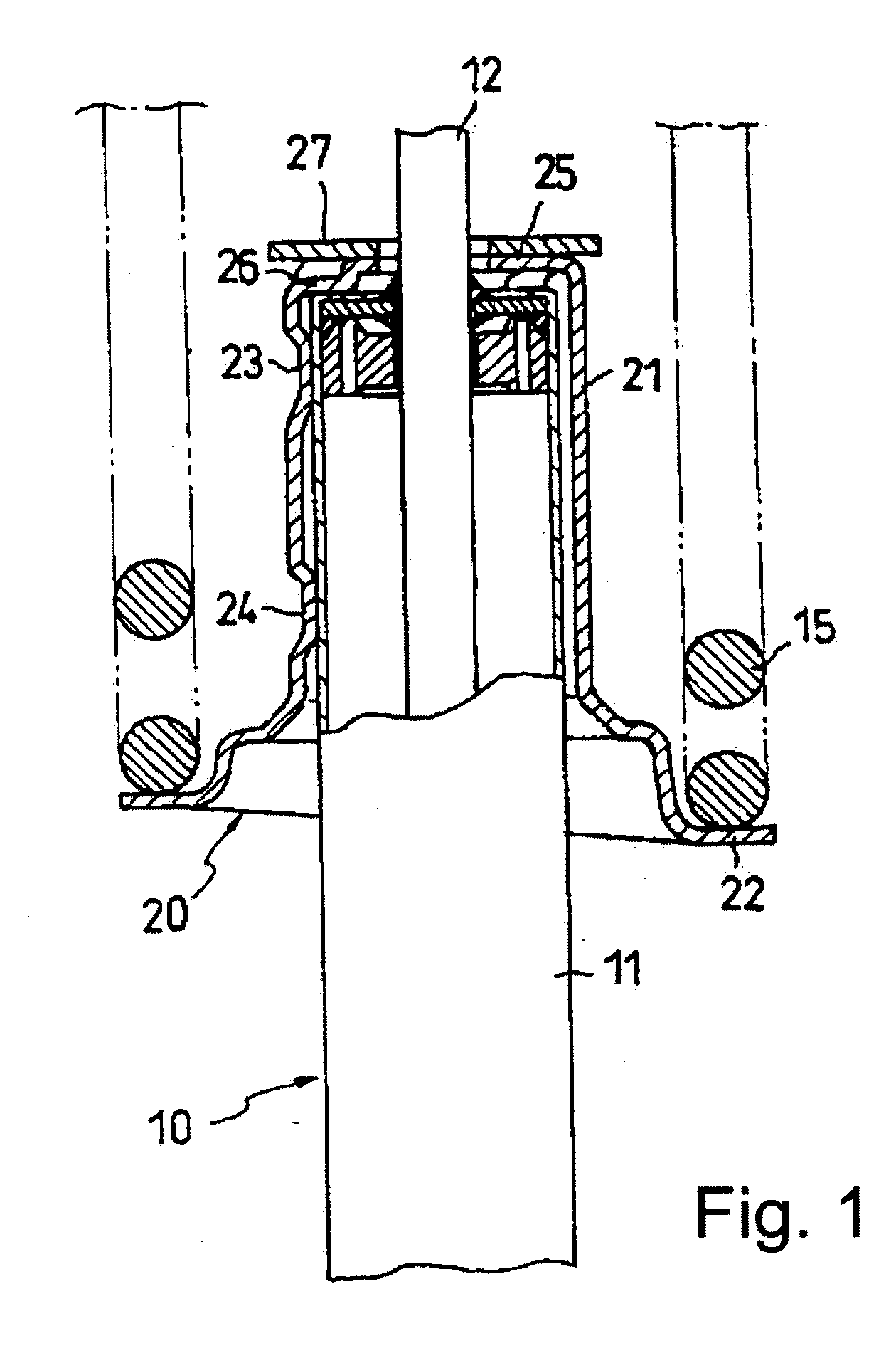
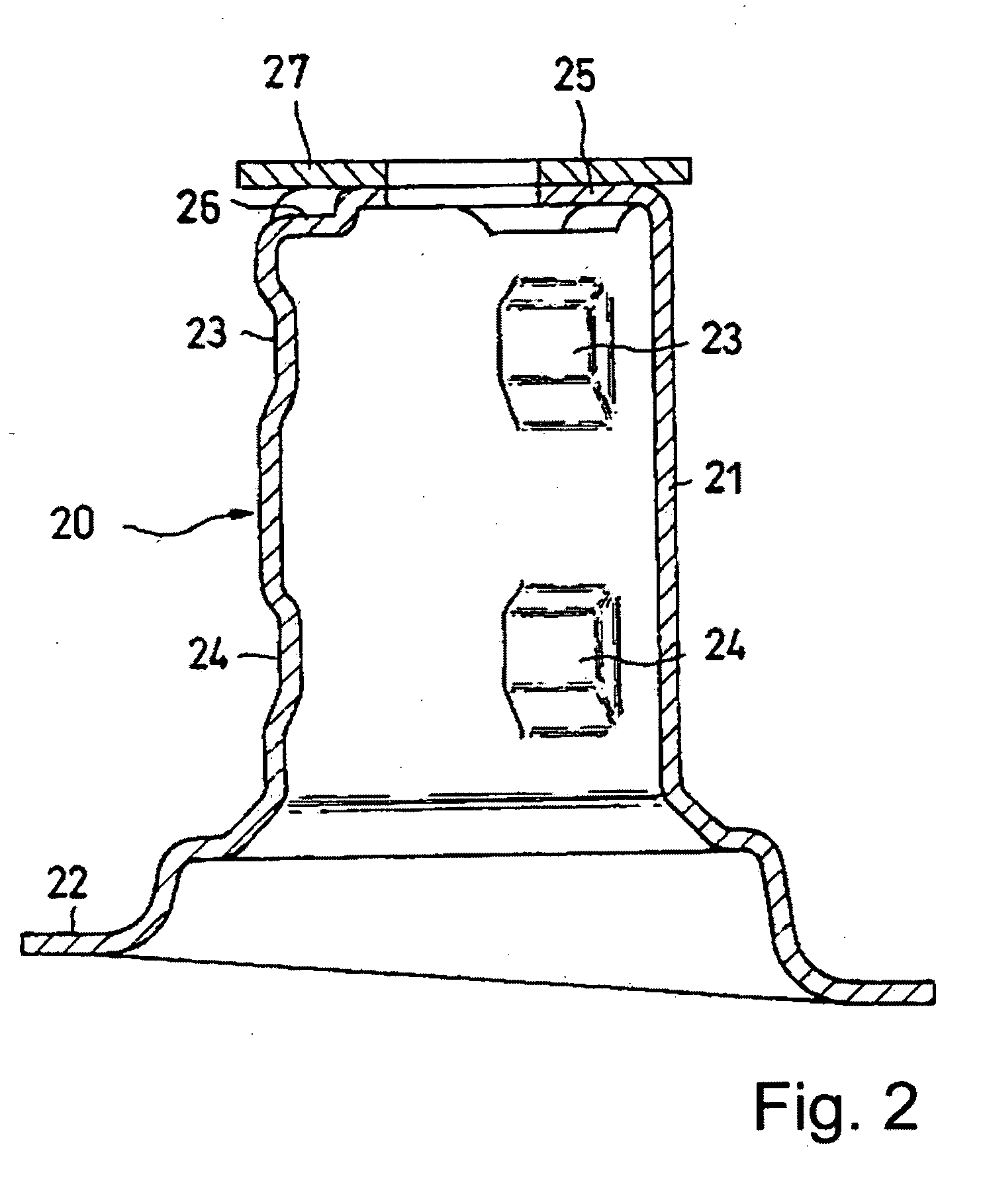
[0018] In one embodiment of the invention, a shock absorber assembly includes a shock absorber 10 and a suspension spring bearing 20 as shown in FIG. 1. The shock absorber 10 comprises a cylinder 11, a free piston (not shown) that forms a working chamber (not shown) and an air chamber (not shown) inside the cylinder 11. A piston (not shown) divides the working chamber into two oil chambers (not shown), with a piston rod 12 connected to the piston. A shock absorber of this configuration is referred to as a single cylinder hydraulic shock absorber.

[0019] In a single cylinder hydraulic shock absorber of this type, the piston is formed with a passage connecting the two oil chambers, and a damping force generating element such as an orifice or a damping valve is mounted in the passage. The shock absorber thus generates a damping force due to the pressure difference between the two oil chambers, this difference being generated by the damping force generating element when the oil flows be...


PUM


Abstract

A shock absorber has a suspension spring bearing fixed securely to a cylinder. The shock absorber includes a cylinder, a suspension spring bearing on the cylinder, and a suspension spring. A suspension spring bearing includes a cylindrical shaped main body that covers an end of the cylinder, an annular spring bearing part formed on a periphery of the main body, a plurality of upper salients that project inwardly from the main body and that are spaced apart at even intervals around the circumference of the main body, in which the upper salients press against the periphery of the cylinder, and a plurality of lower salients that project inwardly from the main body and that are spaced apart at even intervals around the circumference of the main body at locations below those of the upper salients, in which the lower salients press against the periphery of the cylinder.

Description

BACKGROUND OF THE INVENTION [0001] The invention relates to a shock absorber. [0002] In a shock absorber that includes a suspension spring bearing, which bears the bottom end of a suspension spring supporting the weight of a vehicle, the shock absorber comprises, as shown in FIG. 4 for example, a shock absorber D configured in a multi-cylindrical-shape and a suspension spring bearing 2 formed on the periphery of an external cylinder 1 of the shock absorber D. The suspension spring bearing 2 is formed in the shape of a hat, and comprises a cylindrical main body 3 and a suspension spring bearing part 4 extended from the bottom end of the main body 3. [0003] The suspension spring bearing 2 covers the end of external cylinder 1, and is fixed on the external cylinder 1 by applying roll swages on two places, i.e., at the upper and the bottom part, of the main body 3 on its entire periphery as is described, for example, in Japanese Patent Gazette (Tokkyo-kouhou) No. 3,023,958, the entire d...

Claims


Application Information

Patent Timeline
IPC IPC(8): F16F1/12
CPCB60G15/063B60G2204/1242
Inventor HORIBA, KAZUYOSHIMORITA, YUJIKOJIMA, SHIGERUMORIWAKI, FUMIHIROTAKESHITA, EIJI
Owner KYB CORP
Why Eureka
Try Eureka