
Hybrid balloon mold and method of using the mold to form a balloon that is used to manufacture a medical dilatation catheter

a technology of dilatation catheter and hybrid mold, which is applied in the direction of dough shaping, manufacturing tools, catheters, etc., can solve the problems of affecting the quality of dilatation catheters, glass molds that do not provide balloons of molds that do not provide good dimensional precision and accuracy, etc., to achieve more accurate molded balloon dimensions

Inactive Publication Date: 2006-08-10
MEDTRONIC VASCULAR INC
View PDF10 Cites 24 Cited by
  • Summary
  • Abstract
  • Description
  • Claims
  • Application Information

AI Technical Summary

Benefits of technology

[0011] One aspect of the present invention is directed towards a mold for forming a balloon of a balloon catheter including a transparent body portion defining a body region of a mold cavity and metal distal and proximal end caps defining tapering regions and neck regions of the mold c

Problems solved by technology

This glass mold is formed by a labor-intensive process that includes first forming a metal core having the desired shape of the glass mold.
If particular dimensions of the balloon are not precise, problems may occur upon inflation, deflation, or removal of the balloon, which can cause injury or irritation to delicate vascular tissue.
Glass molds do not provide for balloons of good dimensional precision and accuracy because of the way the molds are produced.
For example, molding glass around a core, as describe above, does not allow for measurements to be made of the interior of the mold to ensure proper mold dimensions.
It also does not provide the ability to make fine adjustments to the mold to achieve precise interior dimensions.
If the glass does not shrink uniformly and fittingly against the core, a balloon may have inconsistently formed cones and/or body, bumps on the body and/or an inconsistent outer diameter, which may cause malfunc

Method used


Image

  • Hybrid balloon mold and method of using the mold to form a balloon that is used to manufacture a medical dilatation catheter
  • Hybrid balloon mold and method of using the mold to form a balloon that is used to manufacture a medical dilatation catheter
  • Hybrid balloon mold and method of using the mold to form a balloon that is used to manufacture a medical dilatation catheter

Examples


Embodiment Construction

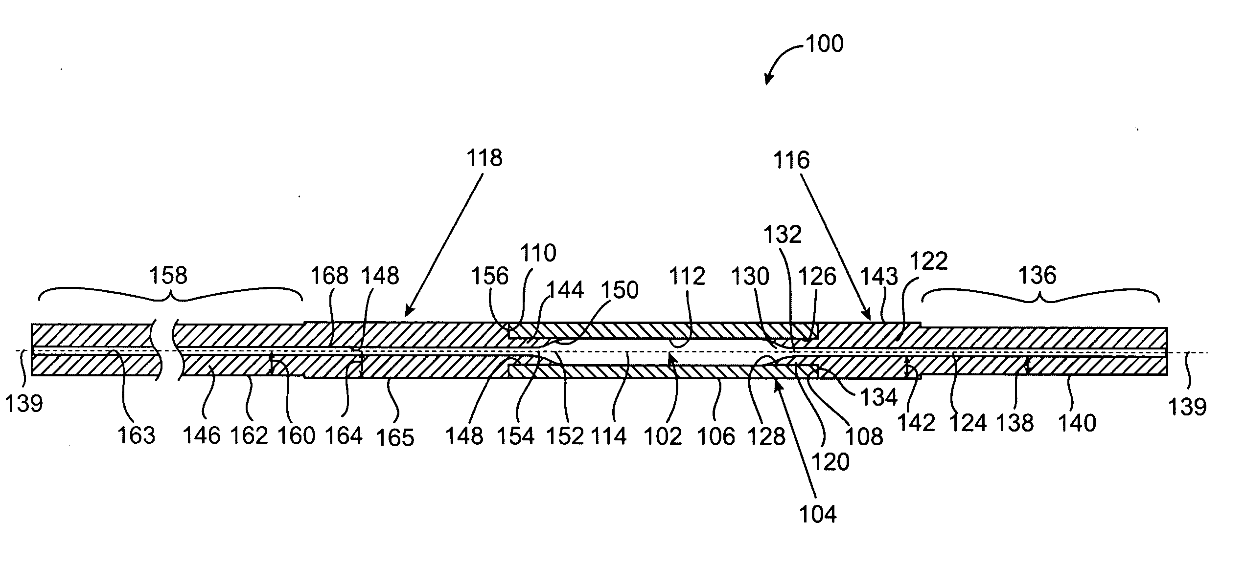
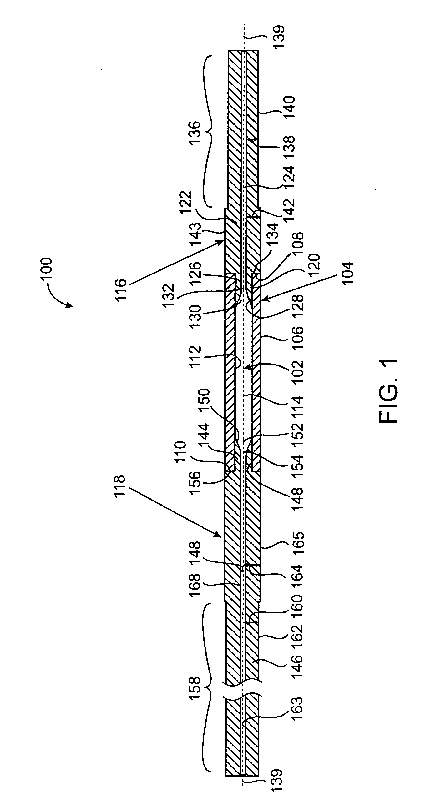
[0021]FIG. 1 is a sectional view of an embodiment of a mold 100 of the present invention. Mold 100 defines a mold cavity 102. Mold 100 is formed with a hollow body portion 104. Body portion 104 is made from a material, such as a transparent or translucent material, such that the mold cavity 102 is visible from an exterior surface 106 of body portion 104. The material may be, for example, glass. Examples of the type of glass used to form body portion 104 include, but are not limited to: borosilicate glass (commercially known under the trade name PYREX), aluminosilicate, fused silica, vitreous silica. In another embodiment, body portion 104 may be made of a plastic material, for example polyetherimide, thermoplastic polyimides (e.g. polybismaleimide polyetherimide, polyamideimide), thermosetting polyimides, polyamides, polyalkyleneterephthalates, polysulphones, polyarylesters, polyphenylenesulfides; liquid crystal polymers; polyketones e.g. polyether ether ketone, polycarbonate, polyo...


PUM

PropertyMeasurementUnit
Forceaaaaaaaaaa
Diameteraaaaaaaaaa
Shapeaaaaaaaaaa

Abstract

A mold for forming a balloon of a balloon catheter including a body portion defining a body region of a mold cavity and distal and proximal end caps defining tapering regions and neck regions of the mold cavity. During the molding process, the mold cavity is visible from an exterior surface of the body portion, which is transparent or translucent. The distal and proximal end caps are metal and can be precision machined in the tapering and neck regions of the mold cavity in order to achieve more accurate molded balloon dimensions. Also disclosed is a method for making a balloon of a balloon catheter using the mold and a balloon made therefrom.

Description

FIELD OF THE INVENTION [0001] The present invention generally relates to a method and mold for forming a balloon for a medical catheter. More particularly, the present invention relates to a hybrid mold design and method of use thereof. BACKGROUND OF THE INVENTION [0002] Inflatable medical balloons associated with balloon catheters are well known in the art, and are commonly used in, for example, percutaneous transluminal coronary angioplasty (PTCA) or delivery of a vascular stent or stent graft. During a PTCA procedure, a balloon catheter is used to dilate arteries obstructed by plaque in order to improve blood flow through the artery. Stents are used as prosthetic devices to support weakened, damaged or diseased vascular walls to avoid catastrophic rupture thereof or to maintain the patency of the vessel. In stent placement procedures in coronary vessels, which often follow PTCA procedures, or in other peripheral vessels of the body, a balloon catheter may be used to radially expa...

Claims


Application Information

Patent Timeline
IPC IPC(8): A21C11/00B29D22/00
CPCA61M25/1029B29C33/3828B29C33/40B29C49/14B29C49/48B29C2033/0005B29C2049/0089B29K2105/258B29K2905/10B29K2905/12B29K2909/02B29K2909/08B29K2995/0026B29K2995/0029B29L2031/7542B29C2949/08
Inventor HESSION, GERARDO'SHAUGHNESSY, DONAGHCLARKE, GERRYLEDWITH, SEAMUSCUMMINS, MICHAELQUINN, NOELVARMA, ASHISH
Owner MEDTRONIC VASCULAR INC
Learn More