
Cycle staging latch with dual phase dynamic outputs for hit logic compare

a technology of cycle staging and output, applied in the direction of pulse generator, pulse technique, electrical apparatus, etc., can solve the problems of too much variability in signal timing and the difficulty in controlling the timing of signals from transistor to transistor, and achieve the effect of reducing the risk of failur

Inactive Publication Date: 2006-08-10
GLOBALFOUNDRIES INC
View PDF9 Cites 2 Cited by
  • Summary
  • Abstract
  • Description
  • Claims
  • Application Information

AI Technical Summary

Benefits of technology

[0007] One object of this invention is the provision of a staging latch which allows for variability for the L1 stage of the latch contents coming from ones macro while allowing the L2 stage to be fired at the appropriate time as needed in order for its contents to be properly compared with the contents from another macro.

Problems solved by technology

With CMOS technologies getting scaled down to smaller dimensions, tracking of signals in time from transistor to transistor is getting harder to control.
With the distances between the macros relatively large, there is problem that too much variability in signal timing will be introduced into the critical path through parameters such as mismatch of channel lengths, threshold voltages, and timing delays.

Method used


Image

  • Cycle staging latch with dual phase dynamic outputs for hit logic compare
  • Cycle staging latch with dual phase dynamic outputs for hit logic compare
  • Cycle staging latch with dual phase dynamic outputs for hit logic compare

Examples


Embodiment Construction

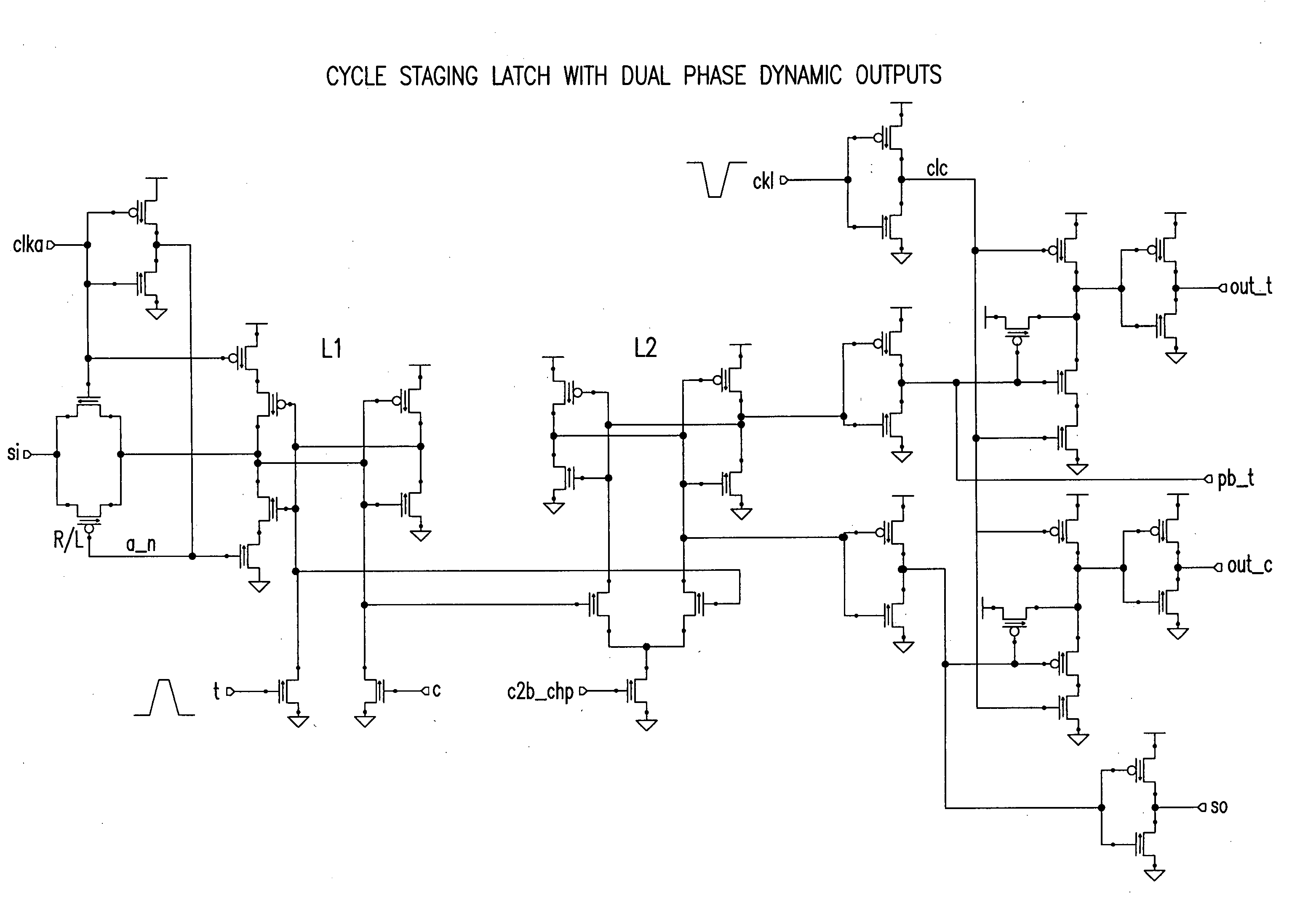
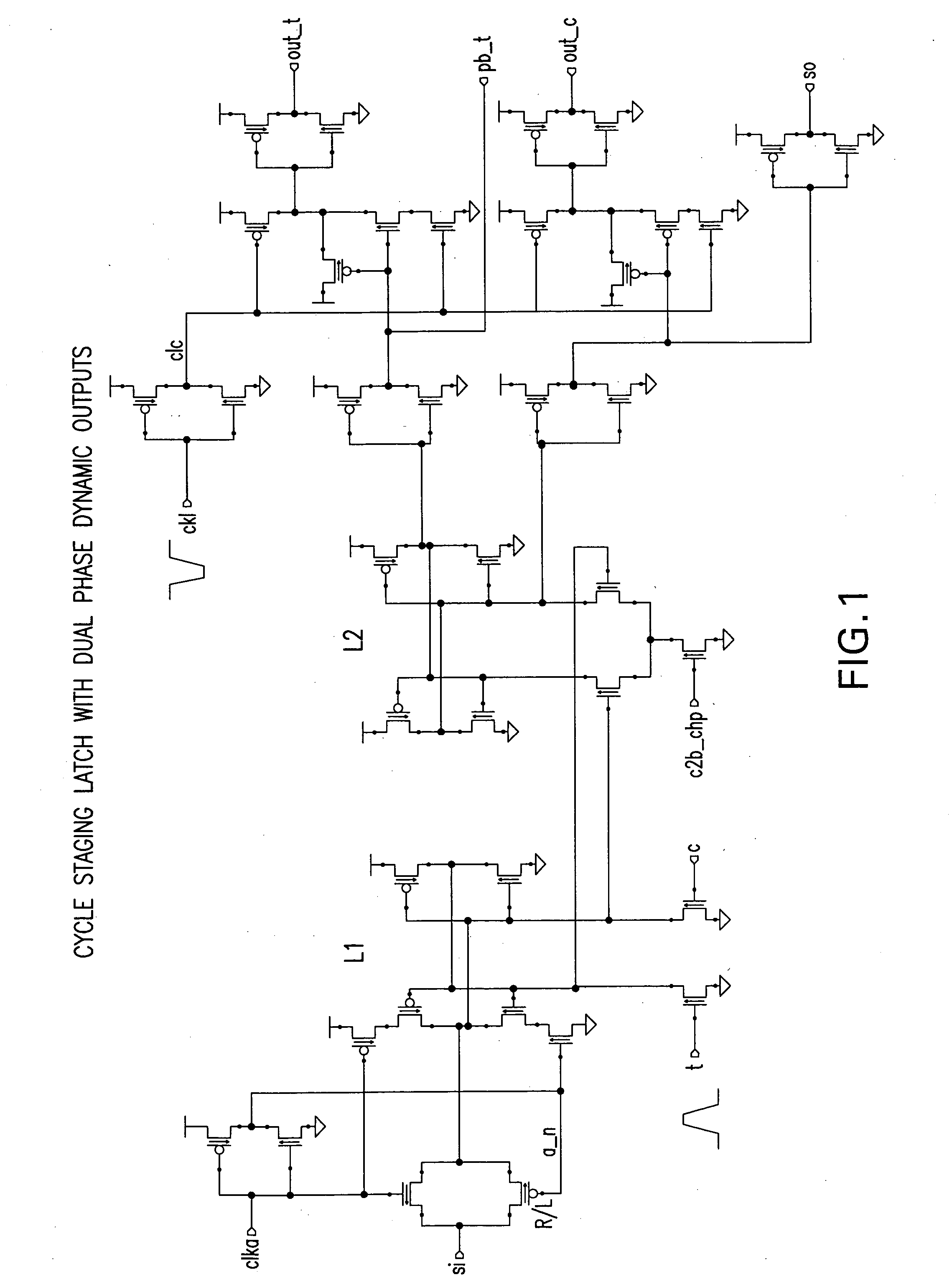
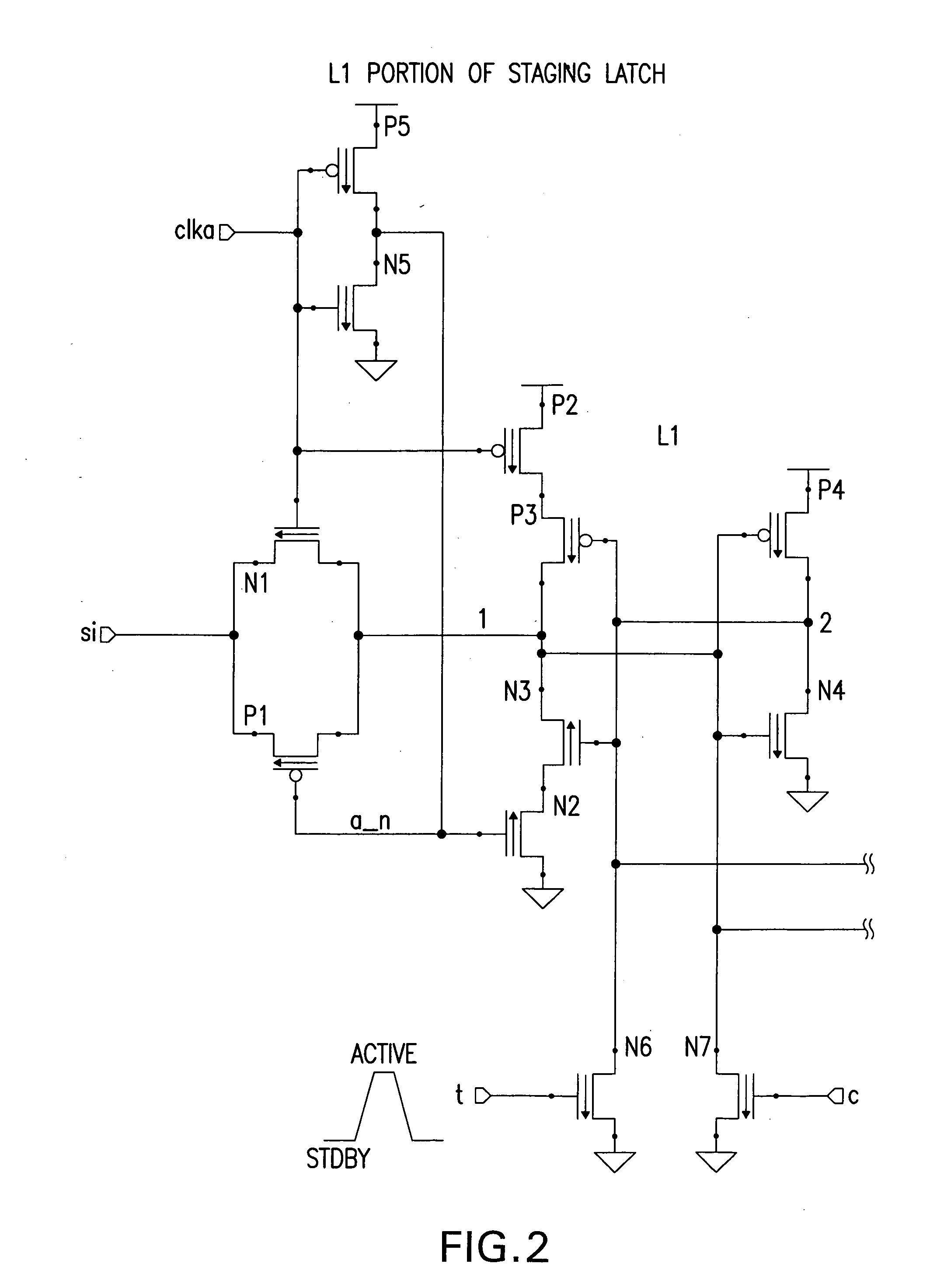
[0014] Referring now to the Figures, because of size, the L1 stage of the L1 / L2 staging latch is shown in FIG. 2 and the L2 stage is shown in FIG. 2. The inputs to the L1 latch are true “t” and its complement ‘c’ from a memory array (not shown). These are dual-rail inputs, meaning either ‘t’ or ‘c’ are active but not both. When the memory array is in a standby mode, both ‘t’ and ‘c’ are off so the contents of the L1 latch are not disturbed. When valid contents are presented from the array, either ‘t’ will turn on transistor N6 to pull down node ‘2’ or, ‘c’ will turn on transistor N7 to pull down node ‘1’. The L1 latch can also be scanned through the ‘si’ port when ‘clka’ is high. The nodes ‘1’ and ‘2’ are static nodes and are coupled as inputs to the gates of transistors N8 and N9 respectively of the L2 latch.

[0015] Either N8 or N9 will be turned on when the L2 clock signal ‘c2b_chp’ is active high. When ‘c2b_chp’ is active, the contents of the L1 will then be stored in the L2 latc...


PUM


Abstract

An output L1 / L2 staging latch has dual rail inputs that up date the state of the L1 latch whenever the inputs are valid. Static outputs of the L1 latch are latched into the L2 by the L2 clock signal. The L2 latch has a static output that is available immediately, and a dual rail dynamic output whose timing is controlled by a clock signal.

Description

CROSS-REFERENCE TO RELATED APPLICATIONS [0001] This application contains subject matter that is related to the subject matter of the following co-pending applications, each of which is assigned to the same assignee as this application, International Business Machines Corporation of Armonk, N.Y. Each of the below listed applications is hereby incorporated herein by reference in its entirety: High Speed Domino Bit Line Interface Early Read and Noise Suppression, Attorney Docket POU9 2004 0217; Global Bit Select Circuit With Dual Read and Write Bit Line Pairs, Attorney Docket POU9 2004 0214; Local Bit Select Circuit With Slow Read Recovery Scheme, Attorney Docket POU9 2004 0224; Global Bit Line Restore Timing Scheme and Circuit, Attorney Docket POU9 2004 1234; Local Bit Select With Suppression, Attorney Docket POU9 2004 0246. BACKGROUND OF THE INVENTION [0002] 1. Field of the Invention [0003] This invention relates to cycle staging latches, and more particularly to and L1 / L2 cycle stag...

Claims


Application Information

Patent Timeline
IPC IPC(8): H03K3/037
CPCH03K3/356139H03K3/356156
Inventor CHAN, YUEN H.CHAREST, TIMOTHY J.JOSHI, RAJIV V.
Owner GLOBALFOUNDRIES INC
Learn More