Oscillator

a technology of oscillator and oscillator, which is applied in the direction of pulse automatic control, pulse generation by logic circuit, pulse technique, etc., can solve the problems of phase noise characteristic of pll and inability of pll to control frequency

Active Publication Date: 2006-08-10
SEMICON COMPONENTS IND LLC
View PDF2 Cites 5 Cited by
  • Summary
  • Abstract
  • Description
  • Claims
  • Application Information

AI Technical Summary

Benefits of technology

[0015] This setting of the limit voltage limits the variation range of the oscillation frequency control voltage, and thereby prevents the oscillation frequency control voltage from entering a saturation region.

Problems solved by technology

That is, there has been a problem that a phase noise characteristic of the PLL is deteriorated.
That is, there has been a problem that the PLL becomes inability to control frequency (deadlock state).

Method used


Image

  • Oscillator
  • Oscillator
  • Oscillator

Examples


Embodiment Construction

[0025] Hereinafter, embodiments of the invention (hereinafter, referred to as embodiment) will be described with reference to the accompanying drawings, wherein like numbers reference like elements.

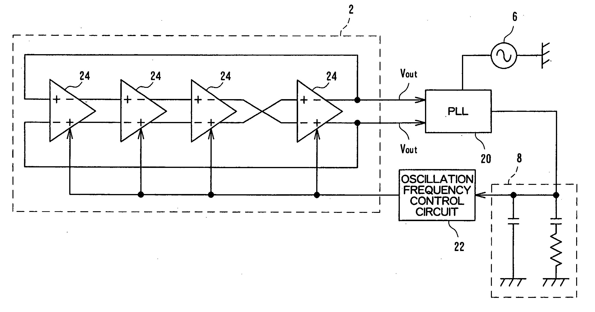
[0026]FIG. 5 is a block diagram schematically showing an oscillator according to an embodiment of the invention. This oscillator is constituted by a current-controlled oscillation circuit 2, a PLL 20, a reference signal source 6, a LPF 8 and an oscillation frequency control circuit 22.

[0027] The current-controlled oscillation circuit 2 is a differential ring oscillator in which interpolating delay circuits 24 are interconnected, for example, in four-stage. The interpolating delay circuits 24 are differential types. In the embodiment, the ring oscillator is configured in even stage. In this case, in one of the interpolating delay circuits 24 which is interconnected, a differential output of a front stage and a differential input of a next stage are connected not to invert a phase, in the...


PUM


Abstract

In the current-controlled oscillator performing an oscillation frequency control by using a differential amplifier circuit, resistors are inserted to each current path of a differential pair of the differential amplifier circuit, and thereby an inclination of output currents Ia, Ib of a differential pair is small in the linear line region. Further, by setting a reference voltage applied to a base of a transistor of one side of the differential pair lowly, the linear region is shifted to low voltage side, and thereby a saturation region of the low voltage side is not occurred. Moreover, when a comparison result of a phase of an output signal of the current-controlled oscillation circuit and a reference signal is converted to an oscillation frequency control voltage Vtune, by limiting an upper limit voltage of the Vtune by an output of a regulator in stead of a positive voltage power source Vcc of common circuit, the Vtune does not move to a saturation region upper than the linear region. According to the current-controlled oscillator, it is possible to prevent deterioration of a phase noise characteristic or deadlock caused by an inclination or a width of the linear region of the output characteristic of the differential amplifier circuit.

Description

CROSS-REFERENCE TO RELATED APPLICATIONS [0001] The priority application number JP2005-030998 upon which this patent application is based is hereby incorporated by reference. BACKGROUND OF THE INVENTION [0002] 1. Field of the Invention [0003] The present invention relates to an oscillator generating an electrical oscillation signal and more particularly, to an oscillator capable of operating stably. [0004] 2. Description of the Related Art [0005]FIG. 1 is a block diagram showing a conventional oscillator. The oscillator is constituted by a current-controlled oscillation circuit 2, a phase-locked loop circuit (PLL) 4, a reference signal source 6, a low pass filter (LPF) 8 and an oscillation frequency control circuit 10. [0006] The current-controlled oscillation circuit 2 is a differential ring oscillator having interpolating delay circuits interconnected in multi-stage in which the transfer time of a signal from an input terminal to an output terminal is variably controlled in respons...

Claims


Application Information

Patent Timeline
Patent Type & Authority Applications(United States)
IPC IPC(8): H03L7/00
CPCH03K3/0322H03K5/13H03K2005/00052H03L7/0995H03L7/0998H03L7/10H03L7/107H03L7/00
Inventor UCHIYAMA, HISAYOSHIWAKAI, FUTOSHI
Owner SEMICON COMPONENTS IND LLC
Why Eureka
Try Eureka