Image display device and image display method

a display device and image technology, applied in the field of display mode, can solve the problems of difficult color adjustment, difficult to perceive true colors, and easy to see color contrast phenomena

Inactive Publication Date: 2006-08-10
PANASONIC CORP
View PDF19 Cites 24 Cited by
  • Summary
  • Abstract
  • Description
  • Claims
  • Application Information

AI Technical Summary

Benefits of technology

[0021] With this kind of display mode, it is possible to suppress the occurrence of color contrast phenomena compared with a conventional display mode which displays the same picture side-by-side, and the user can accurately perceive colors and perform adjustment.
[0024] According to this structure, the image display device can easily realize a color conversion mechanism by using a look-up table as a color conversion table which stores pre-conversion colors and converted colors mapped to one another.
[0028] According to this structure, it is possible to realize a structure which splits a display into two areas and specifies signals for each area through a simple structure which uses a latch storing the coordinate value of a boundary position and a counter which counts the input clocks of image signals.
[0040] According to this structure, it is possible to set a predetermined distance for the separation between the position specified by a mouse operation, etc. and the boundary position.

Problems solved by technology

However, color contrast phenomena readily occur, making color adjustment difficult with the display mode of the above document.
In the case of the display mode in the above document, when looking for a period of time at the image in the reference window, then looking at the image in the task window, the afterimage of the reference window appears superimposed on the image in the task window as a result of successive contrast, and perceiving true colors thus becomes difficult.
Also, given that the size, the contour lines, and the shapes in the image of the reference window and the image in the task window match exactly, the afterimage is intensified by looking at the two windows one after another, making color adjustment all the more difficult.
In the case of the display mode in the above document, since the device scales down the image for full-screen display to, fit the window size, characteristics of the image colors appear weakened, making it impossible to accurately perceive the colors.

Method used


Image

  • Image display device and image display method
  • Image display device and image display method
  • Image display device and image display method

Examples


embodiment 1

Brief Summary

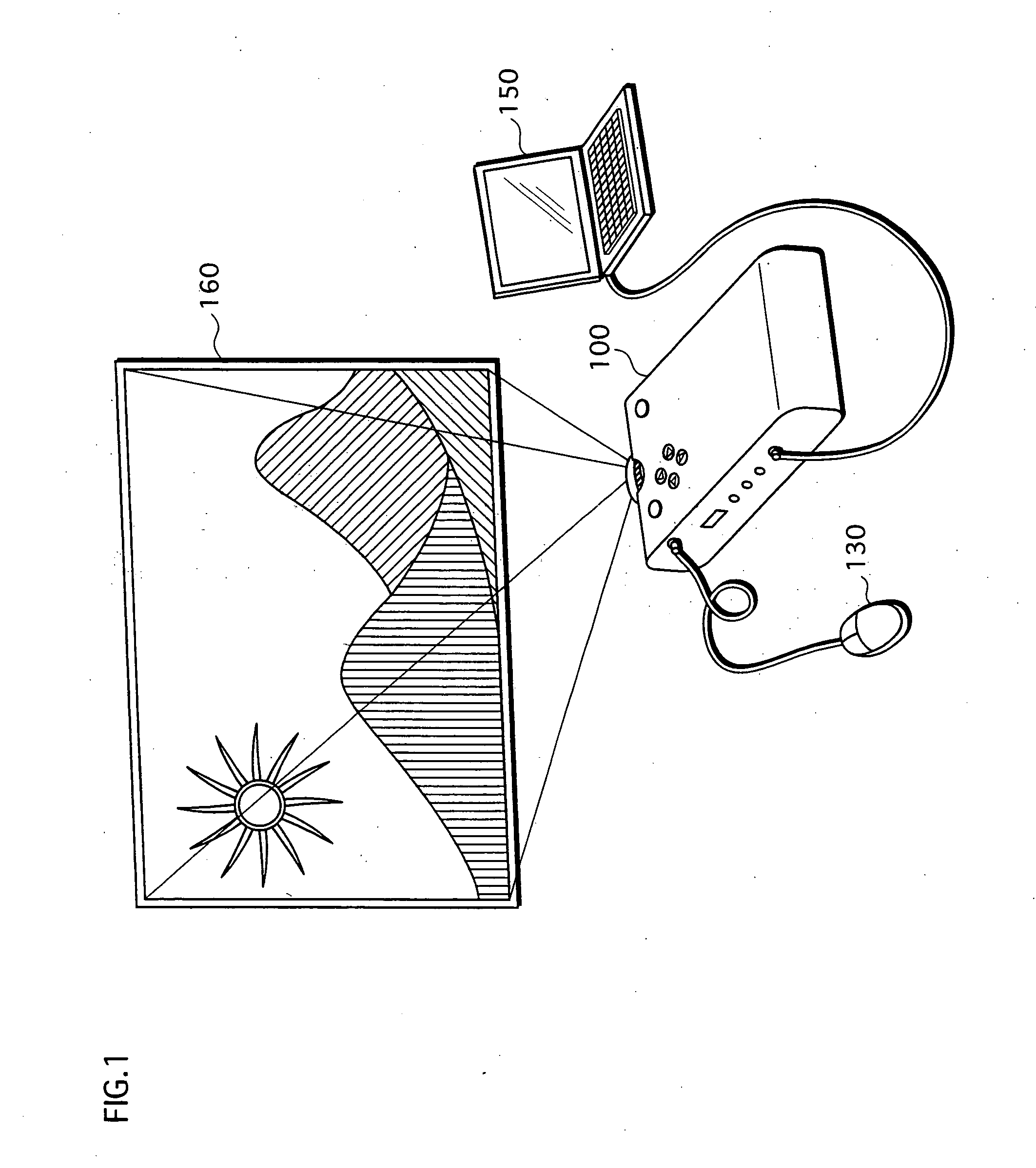
[0062]FIG. 1 shows a mode of use of a projector, being an embodiment of the present invention.

[0063] A projector 100 in this figure internally processes image signals from a PC 150 connected to an input terminal, develops the processed signals on a liquid crystal panel, and enlarges the developed image for display on a screen 160. If instructed during display to perform color adjustment by an operation of a user's mouse 130, the projector 100 divides the image displayed on the screen 160 vertically into two areas, displays one area using the original colors, and displays the other area after performing color conversion according to colors instructed by the user.

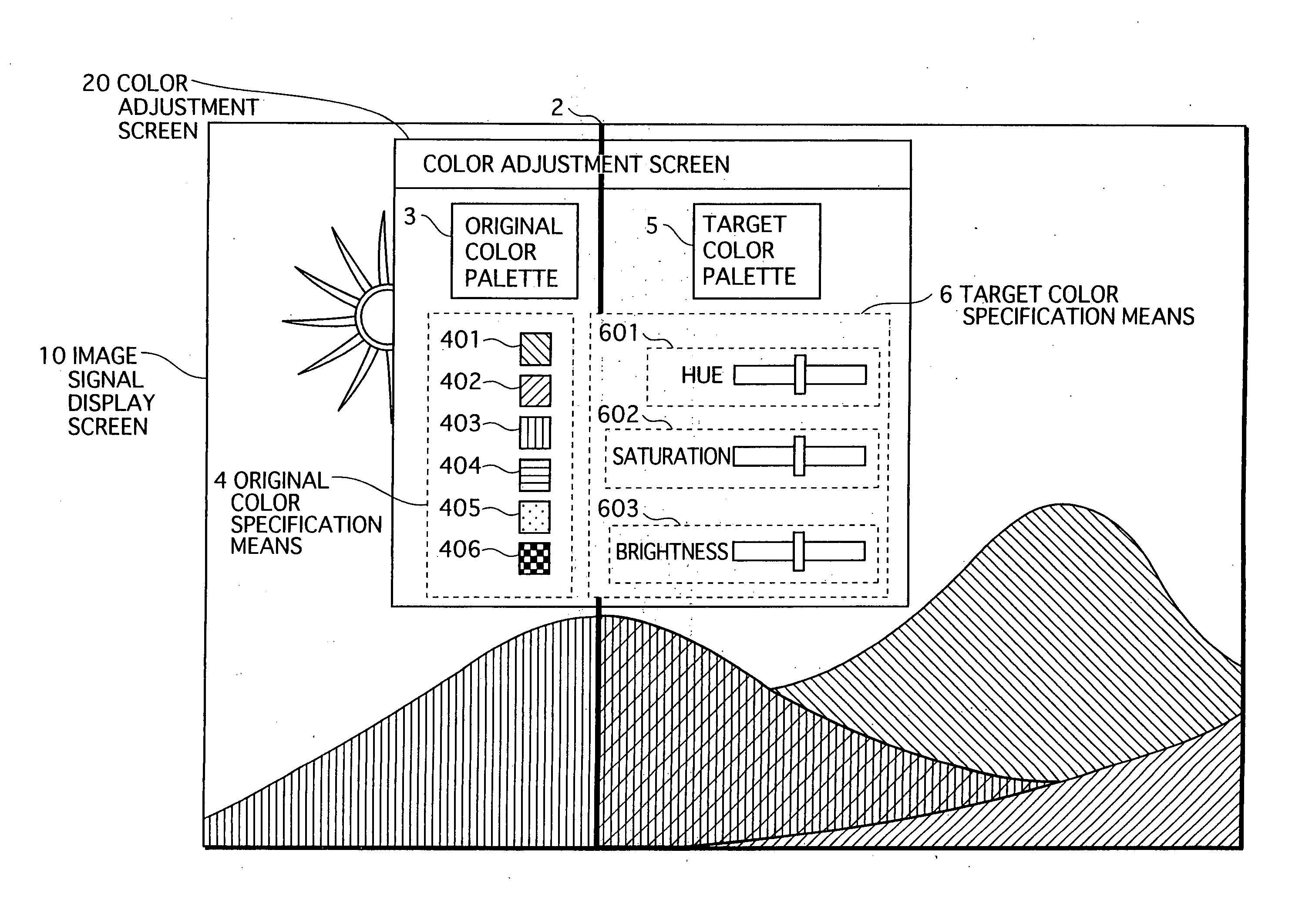
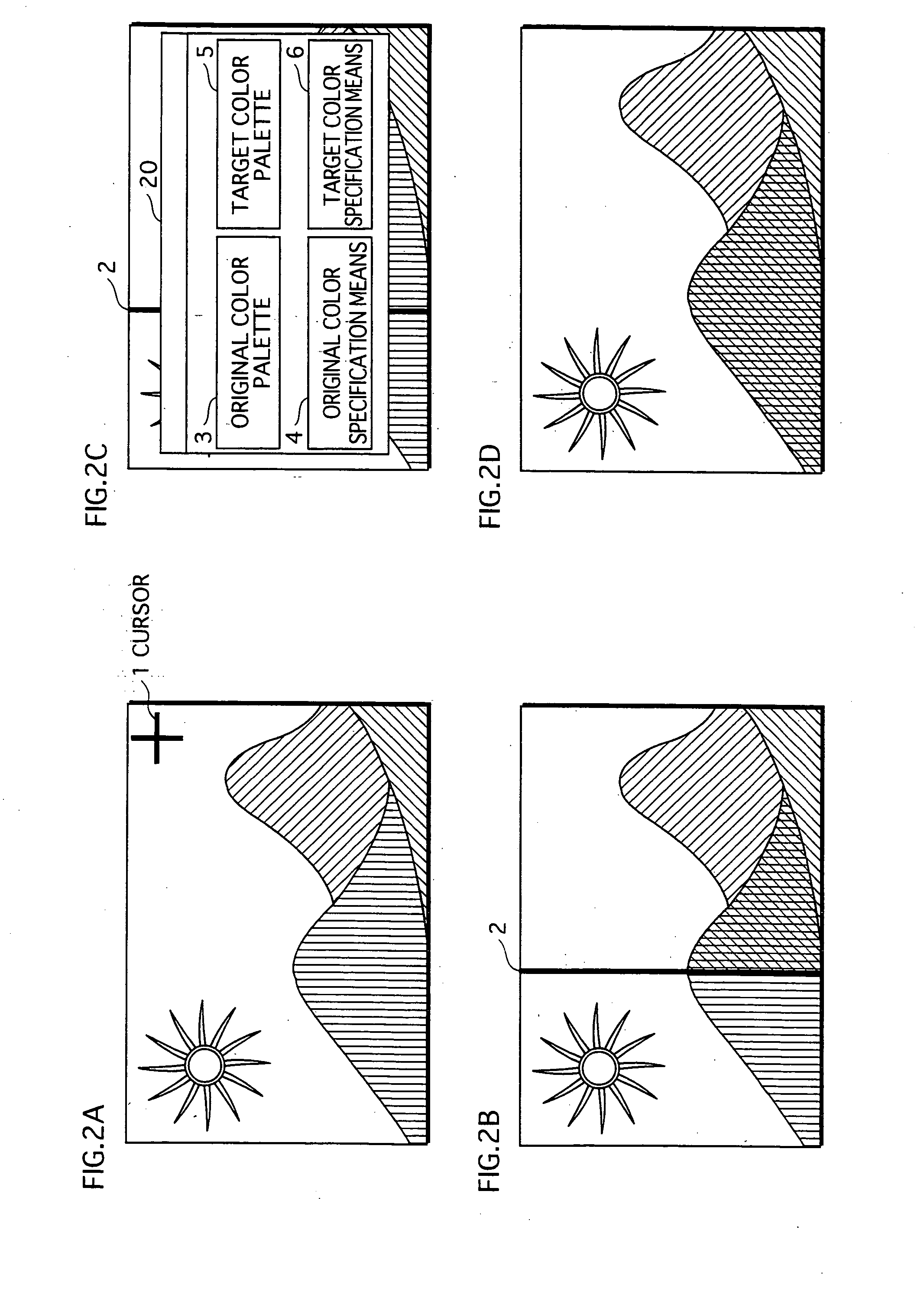
[0064]FIGS. 2A to 2B show an example of a display mode during color adjustment.

[0065] If the user moves the mouse 130 while an image is being displayed, a cursor is displayed on the image as shown in FIG. 2A. When the mouse is used to move the cursor and left-clicked at a suitable position, a boundary line 2...


PUM


Abstract

A projector capable of performing color adjustment through a display mode which reduces the occurrence of color contrast phenomena. A main microcontroller (70), which determines a boundary position for dividing the display into a first area and a second area, and a switch control unit (56) switch the output of an output selector (55) according to pixel positions, so that image signals of a part of an image to be displayed in the first area are converted by a color conversion LUT (52) before being output, while image signals of a remaining part of the image to be displayed in the second area are directly output.

Description

TECHNICAL FIELD [0001] The present invention relates to a display mode for color-adjusting an image displayed on a display medium such as a screen or display by a projector, DVD player, computer, etc. BACKGROUND ART [0002] Devices which display an image on a display medium such as a screen or display commonly include a color adjustment function for adjusting colors according to a user's instruction. [0003] A color adjustment function is particularly necessary with projectors that project an image based on image signals input with various color schemes onto a wide variety of screen types, since display colors are readily altered depending on the combination of the color scheme and the screen. [0004] A conventional color adjustment function is described in Japanese Patent Application Publication No. 2002-262218. [0005] An image correction device in this document disposes a reference window and a task window side-by-side on a single display screen, and displays the same image in both w...

Claims


Application Information

Patent Timeline
Patent Type & Authority Applications(United States)
IPC IPC(8): G09G5/02H04N9/31H04N9/64
CPCH04N9/3182H04N9/3197
Inventor KIMOTO, TAKAYUKISEKI, YOSHIOKUWABARA, AKIHIRO
Owner PANASONIC CORP
Why Eureka
Try Eureka