Constant current driver, back light source and color liquid crystal display

a driver and constant current technology, applied in the direction of electric variable regulation, process and machine control, instruments, etc., can solve the problems of complicated and expensive circuitry for driving

Inactive Publication Date: 2006-08-10
SONY CORP
View PDF16 Cites 46 Cited by
  • Summary
  • Abstract
  • Description
  • Claims
  • Application Information

AI Technical Summary

Benefits of technology

[0012] In the constant current driving unit, backlight light source unit and the color liquid crystal display apparatus, according to the present invention, the gate potential setting circuit, provided to bypass circuits, composed of thyristors connected in parallel with plural series connected devices, applies such gate potential which will turn off the thyristors during the normal operation of the series-connected devices, and which, when one or more of the series connected devices are in open state, will turn on the thyristors connected to the devices which are now in the opened state. Thus, when the string of plural series-connected devices, such as light emitting diodes, is driven with the constant current, and one or more of the devices suffer from OPEN-mode malfunctions, the device current which would pass through the malfunctioning site may be detoured to automatically avoid the disconnected status of the malfunctioning site.
[0013] Other objects and advantages of the present invention will become more apparent from the following explanation of a preferred embodiment thereof especially when read with reference to the drawings.

Problems solved by technology

The result is the complicated and expensive circuitry for driving.

Method used


Image

  • Constant current driver, back light source and color liquid crystal display
  • Constant current driver, back light source and color liquid crystal display
  • Constant current driver, back light source and color liquid crystal display

Examples


Embodiment Construction

[0027] Referring to the drawings, a present embodiment of the present invention will be explained in detail. It is noted that the present invention is not limited to the embodiment now explained and may optionally be changed without departing from the scope of the invention.

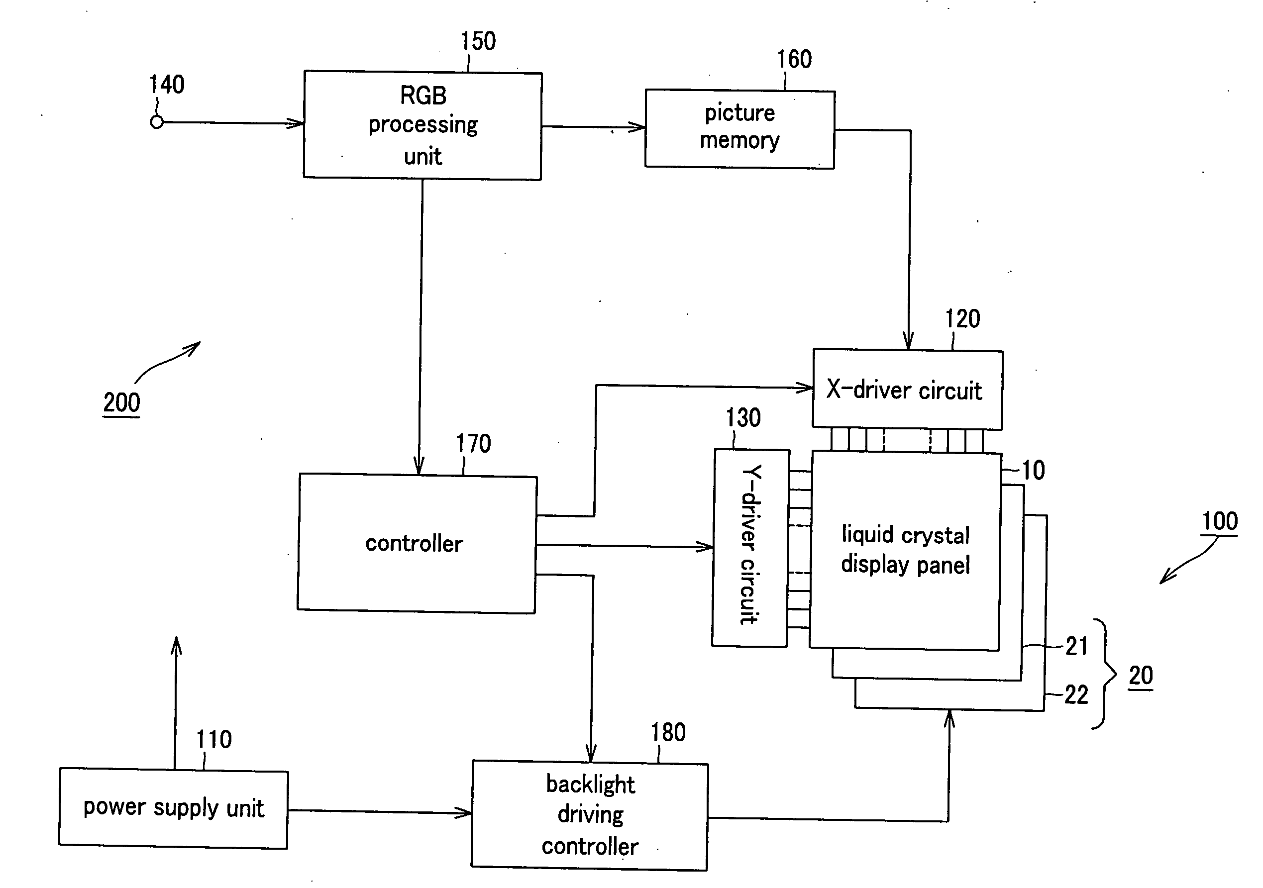
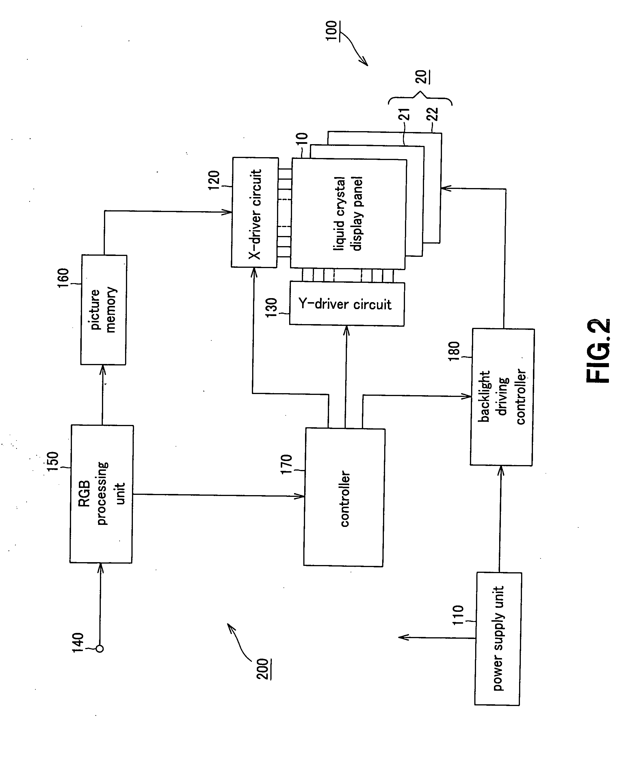
[0028] The present invention is applied to a color liquid crystal display apparatus 100 of the backlight system, configured as shown in FIG. 1.

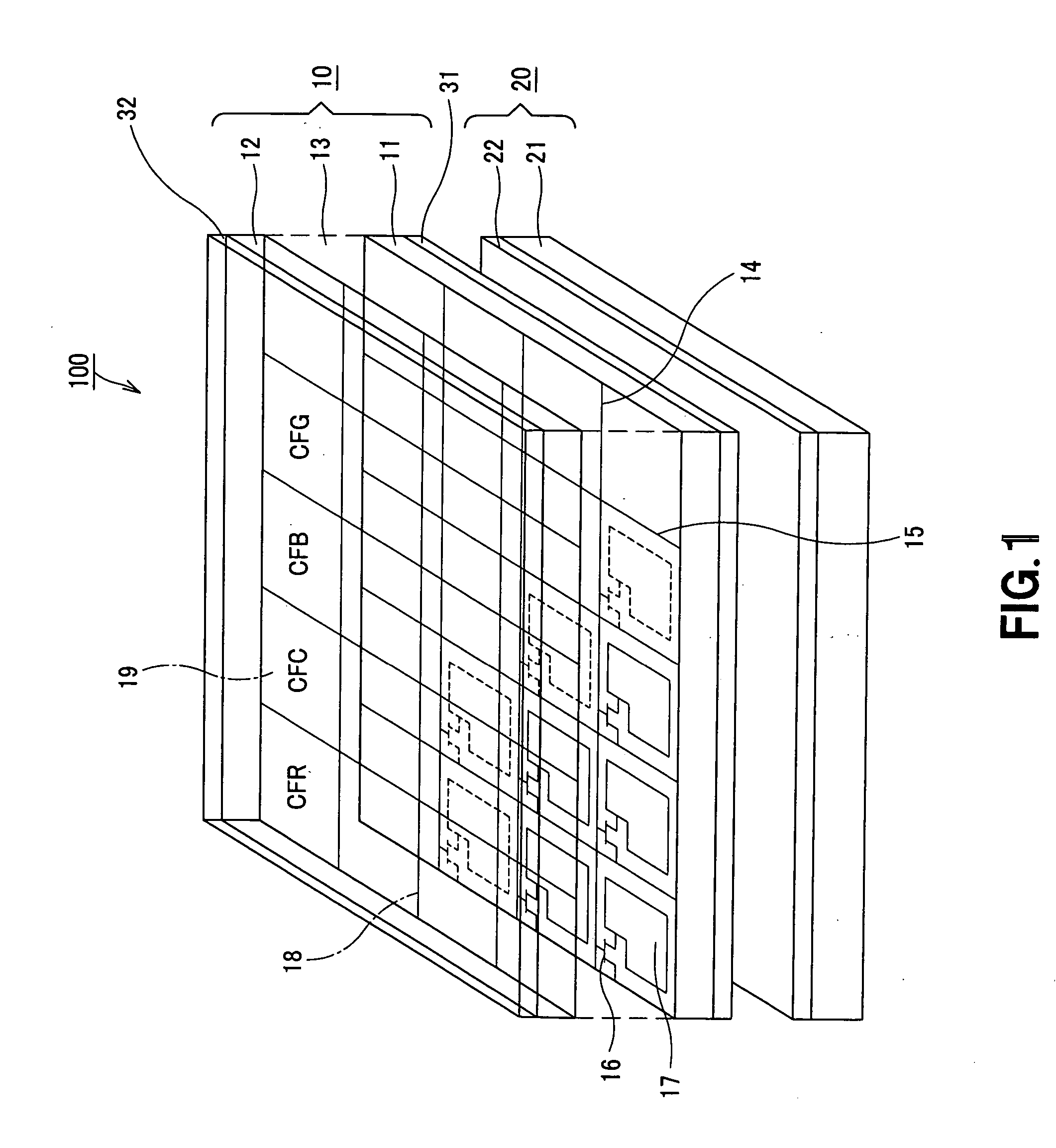
[0029] This color liquid crystal display apparatus 100 is made up by a light transmitting type color liquid crystal display panel 10 and a backlight light source unit 20 provided on the back side of the color liquid crystal display panel 10.

[0030] The light transmitting type color liquid crystal display panel 10 is made up by a TFT substrate 11 and a counter-electrode substrate 12 facing each other with a gap in-between. Within this gap, there is provided a liquid crystal layer 13 composed e.g. of twisted nematic (TN) liquid crystal. The TFT substrate and the counter-el...


PUM

PropertyMeasurementUnit
currentaaaaaaaaaa
voltageaaaaaaaaaa
gate potentialaaaaaaaaaa

Abstract

Disclosed is a constant current driving unit for constant current driving a plural number of series connected light emitting diodes by a pulse-width modulating constant current driving circuit. Bypass circuits (80A) to 80(E), made up by a plural number of thyristors (81A) to (81E), each connected in parallel with each of series-connected light emitting diodes (41A) to (41E), are provided with gate potential setting circuits (83A) to (83E). These gate potential setting circuits afford to the thyristors a gate potential value such that, when the series-connected light emitting diodes (41A) to (41E) are operating as normally, the thyristors (81A) to (81E) are in the off-state. The gate potential setting circuit affords to the thyristors another gate potential value such that, when the light emitting diodes (41A) to (41E) are in the open state, the thyristors connected in parallel with the light emitting diodes (41A) to (41E) in the opened state will be in a turned-on state.

Description

TECHNICAL FIELD [0001] This invention relates to a constant current driving unit for constant current driving a plural number of series-connected light emitting diodes (LEDs) using a pulse width modulating constant current driving circuit. This invention also relates to a backlight light source unit and a color liquid crystal display apparatus, driven by this constant current driving unit. [0002] This application claims subject-matter related to Japanese Patent Application JP 2004-124795, filed in the Japanese Patent Office on Apr. 20, 2004, the entire contents of which are incorporated herein by reference. BACKGROUND ART [0003] Recently, the tendency is towards using a display of thin thickness, as exemplified by a liquid crystal TV or plasma display (PDP: Plasma Display Panel). In particular, most of the displays for mobile use are liquid crystal displays for which faithful color reproducibility is desirable. On the other hand, the mainstream of the backlight for the liquid crysta...

Claims


Application Information

Patent Timeline
Patent Type & Authority Applications(United States)
IPC IPC(8): G02F1/133G09G3/34H01L33/00G02F1/13357H05B44/00
CPCG02F1/133603G09G3/342G09G2300/0452G09G2320/064H05B33/0818H05B33/0857H05B33/089H05B45/20H05B45/37H05B45/54G02F1/133
Inventor FURUKAWA, NORIMASA
Owner SONY CORP
Why Eureka
Try Eureka