

Method and apparatus for determining reference levels and flatness of a surface
a reference level and flatness technology, applied in the field of lasers, can solve the problems of tedious and error-prone process, difference between the two readings, and the error level of the counter
- Summary
- Abstract
- Description
- Claims
- Application Information
AI Technical Summary
Benefits of technology
Problems solved by technology
Method used
Image

Examples
Embodiment Construction
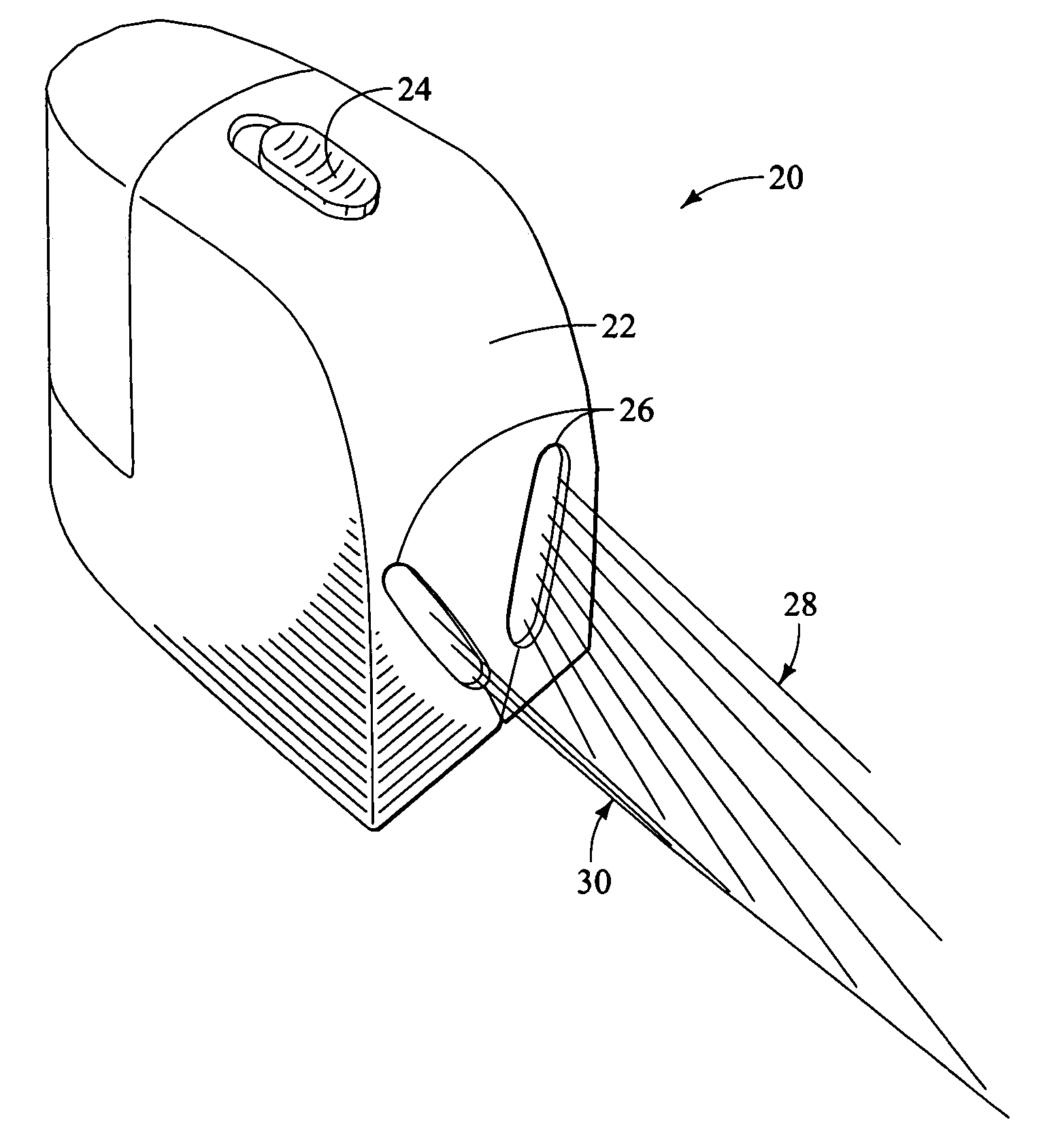
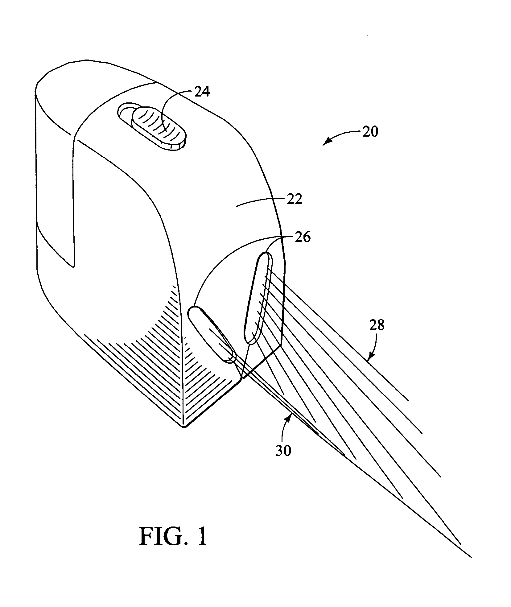
[0024] Embodiments of the present invention are useful to perform several important tasks that are important in the building and home improvement trades, in addition to related tasks in other arts. The embodiments described in this patent can easily transfer heights across a room, level surfaces such as countertops and the like and determine the flatness of a surface. These tasks can be done efficiently and accurately using various preferred embodiments of the present invention. These embodiments utilize many known components of laser technology, but by virtue of their elegant design, produce visual indicia that represents topographically accurate information of the surface which is being examined. Stated in other words, the displayed lines, i.e., the lines resulting from the laser beams impinging on the surfaces on which they are projected, provide visually intuitive information that represents the shape of the surface being examined.
[0025] Referring to the drawings and particular...
PUM
 Abstract
Description
Claims
Application Information