Heat pump type drying apparatus drying apparatus and drying method
- Summary
- Abstract
- Description
- Claims
- Application Information
AI Technical Summary
Benefits of technology
Problems solved by technology
Method used
Image
Examples
first embodiment
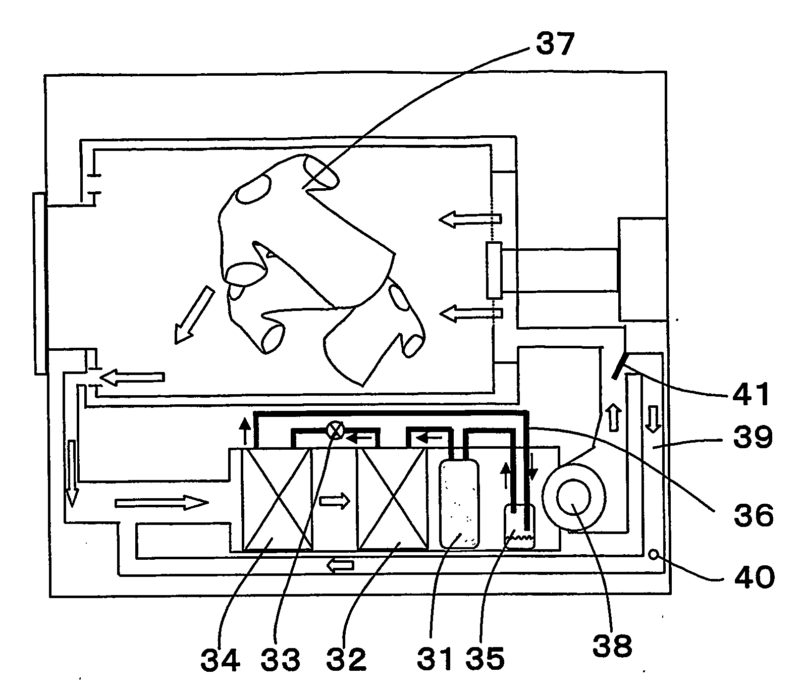
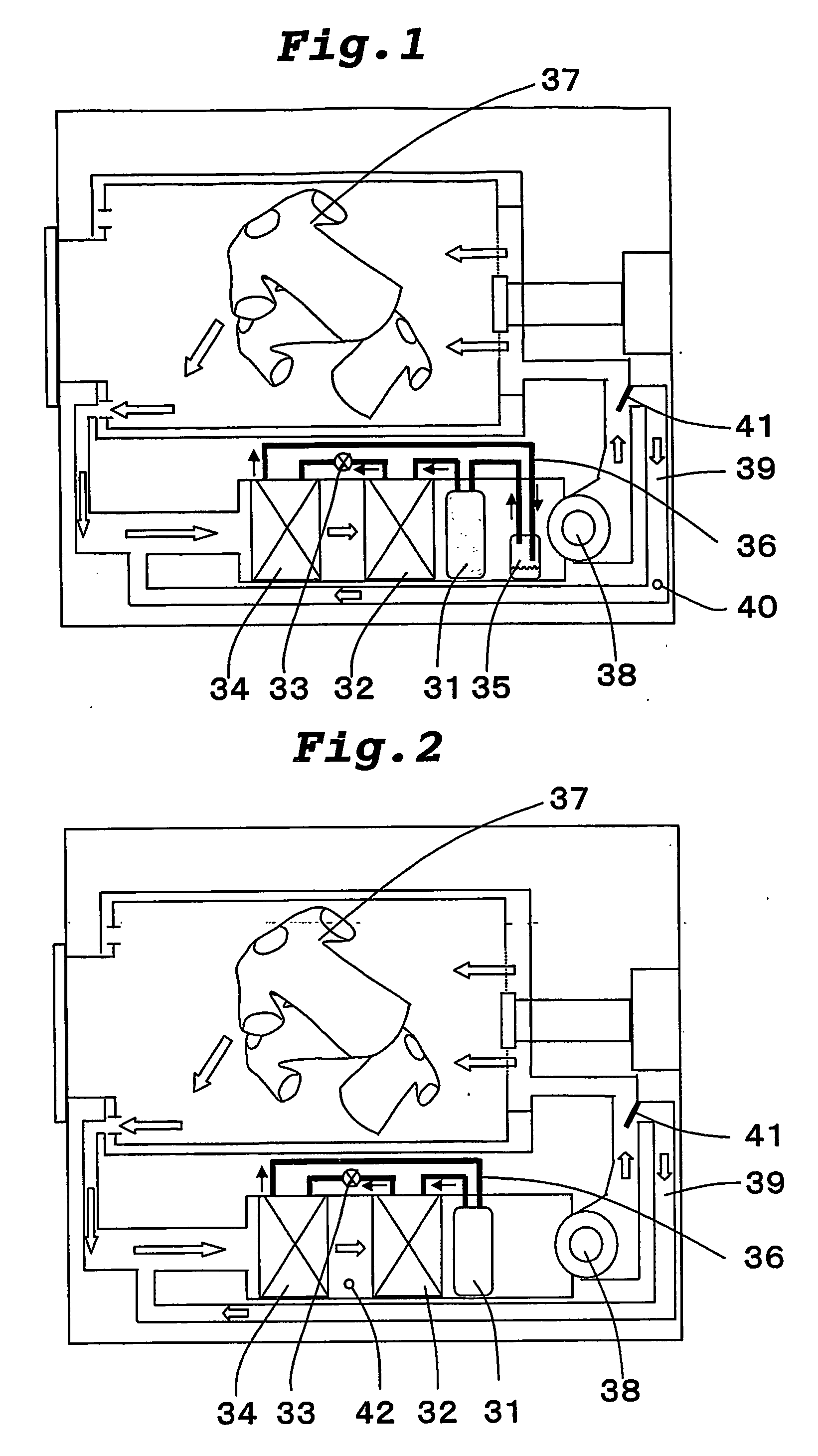
[0044]FIG. 1 is a block diagram of a heat pump type drying apparatus according to a first embodiment of the present invention. In FIG. 1, a heat pump apparatus is constituted by connecting a compressor 31, a radiator 32, an expansion valve 33 provided as an expansion mechanism, an evaporator 34 and a refrigerant accommodating container 35 to one another through pipes 36, and by charging a refrigerant thereinto. As the refrigerant, a refrigerant which can be brought into the supercritical state on the radiation side (compressor 31, discharge section to radiator 32 to expansion valve 33, inset section), e.g., CO2 refrigerant is charged. A reference number 37 represents a subject to be dried. For example, the subject could be clothes, bathroom space or any other item which needs to be dried. A reference number 38 represents a fan, a reference number 39 represents a bypass circuit, a reference number 40 represents a bypass circuit air flow rate detecting device, a reference number 41 re...
second embodiment
[0055]FIG. 2 is a block diagram of a heat pump type drying apparatus according to a second embodiment of the invention. In FIG. 2, common constituent elements shown in FIG. 1 are designated with the same reference symbols, and explanation thereof will be omitted. A heat pump apparatus is constituted by connecting the compressor 31, the radiator 32, the expansion valve 33 and the evaporator 34 to one another through pipes 36, and by charging the refrigerant thereinto. As the refrigerant, a refrigerant which can be brought into a supercritical state on the radiating side, such as a CO2 refrigerant for example, is charged.
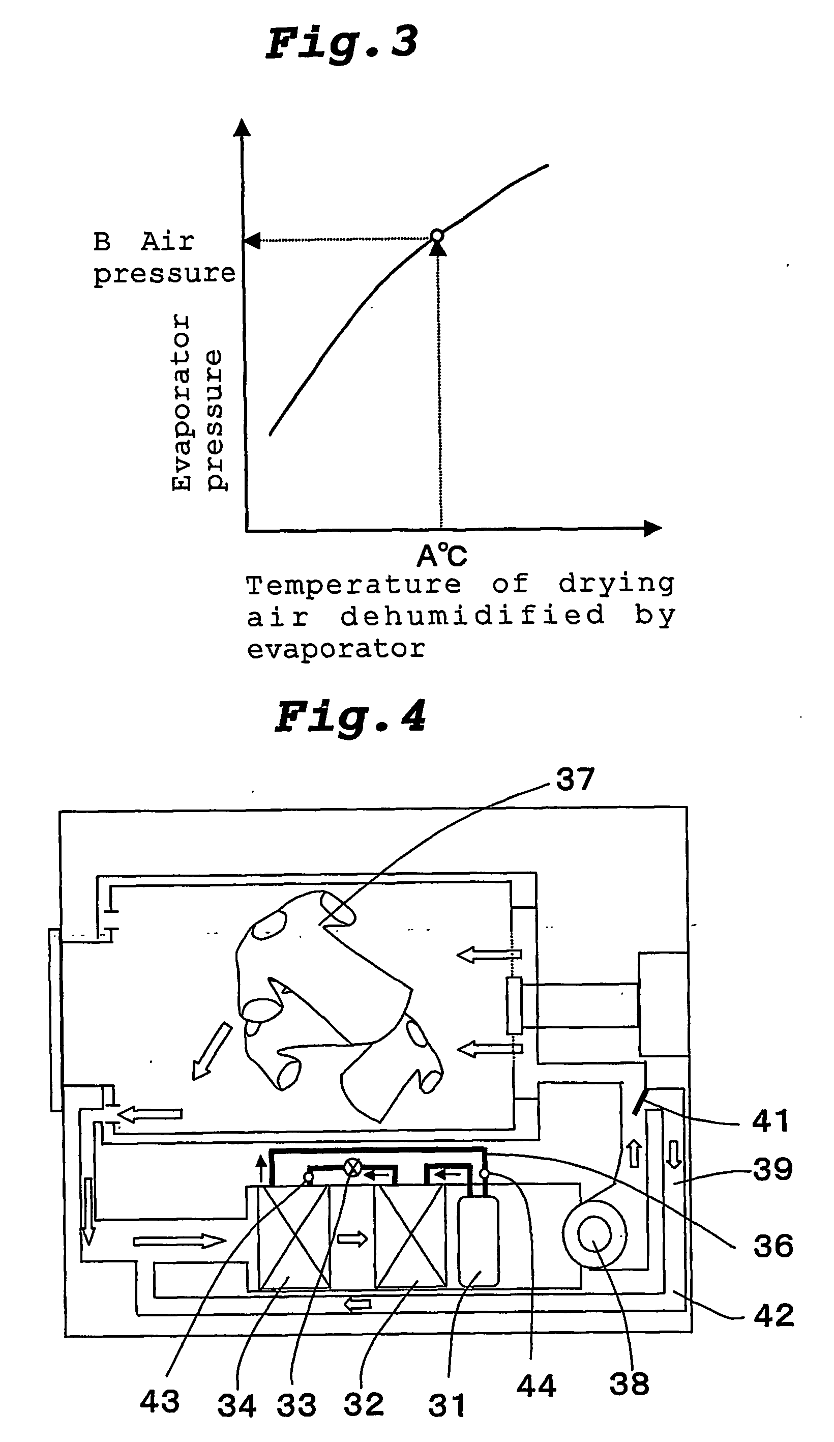
[0056] In this embodiment, in a duct between the radiator 32 and the evaporator 34, there are provided a temperature sensor 42 which detects a temperature of a drying air dehumidified by the evaporator 34, and the open / close valve 41 capable of adjusting the flow rate of the drying air which flows into the bypass circuit using a value detected by the temperature sens...
third embodiment
[0060]FIG. 4 is a block diagram of a heat pump type drying apparatus according to a third embodiment of the invention. In FIG. 4, common constituent elements shown in FIG. 1 are designated with the same reference symbols, and explanation thereof will be omitted. A heat pump apparatus is constituted by connecting the compressor 31, the radiator 32, the expansion valve 33 and the evaporator 34 to one another through pipes 36, and by charging the refrigerant thereinto. As the refrigerant, a refrigerant which can be brought into a supercritical state on the radiating side, such as a CO2 refrigerant for example, is charged.
[0061] This embodiment has the bypass circuit 39 through which a portion of the drying air heated by the radiator 32 flows to an inlet of the evaporator 34 without coming into contact with the subject 37, a super heat detecting device (a for example, temperature sensor 43) for detecting the temperature of refrigerant around the inlet of the evaporator 34 and a tempera...
PUM
 Abstract
Description
Claims
Application Information
 - R&D
- Intellectual Property
- Life Sciences
- Materials
- Tech Scout
- Unparalleled Data Quality
- Higher Quality Content
- 60% Fewer Hallucinations
Browse by: Latest US Patents, China's latest patents, Technical Efficacy Thesaurus, Application Domain, Technology Topic, Popular Technical Reports.
© 2025 PatSnap. All rights reserved.Legal|Privacy policy|Modern Slavery Act Transparency Statement|Sitemap|About US| Contact US: help@patsnap.com


