

Gas chromatograph and quartz crystal microbalance sensor apparatus
a quartz crystal and microbalance sensor technology, applied in the field of sensing devices, can solve the problems of high cost, increased mass loading of saw sensor, and higher frequency means
- Summary
- Abstract
- Description
- Claims
- Application Information
AI Technical Summary
Benefits of technology
Problems solved by technology
Method used
Image

Examples
Embodiment Construction
[0023] The particular values and configurations discussed in these non-limiting examples can be varied and are cited merely to illustrate at least one embodiment and are not intended to limit the scope thereof.
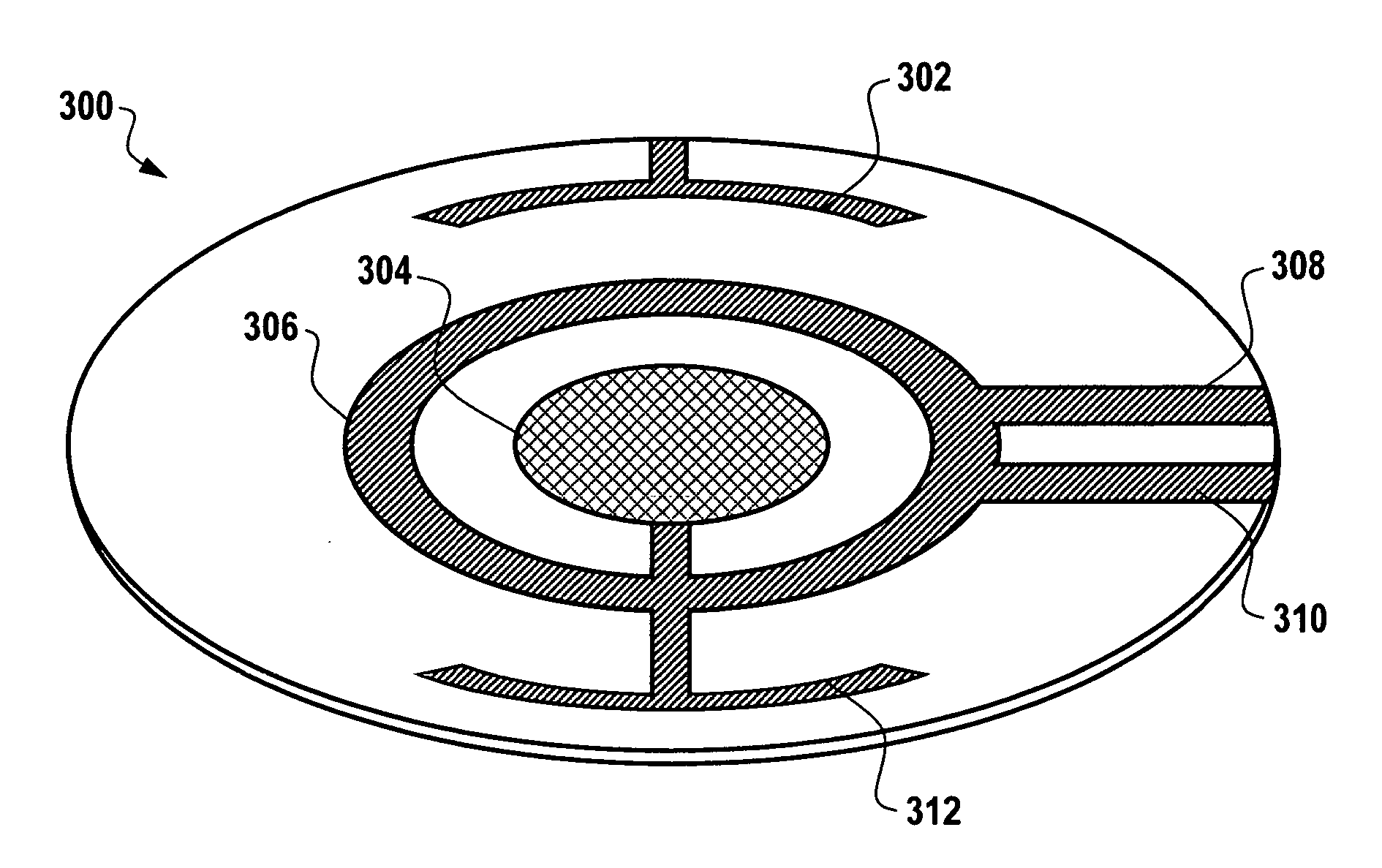
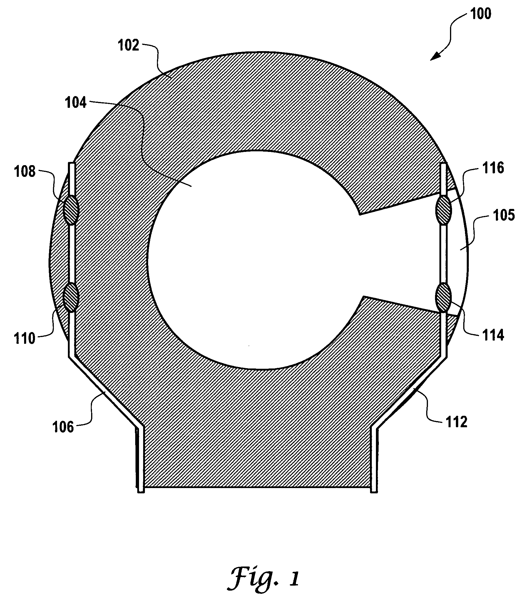
[0024]FIG. 1 illustrates a QCM detector 100 that can be implemented in accordance with an embodiment. QCM detector 100 generally utilizes a vibration amplitude / overtones controlled quartz material 104 to absorb vapors as they exit a GC capillary column of a GC device. Sensitivity of QCM detector 100 can be controlled by selecting the vibration modes, vibration amplitude, substrate temperature and / or overtones during chromatography.
[0025] The quartz material 104 is generally disposed within a circular region 102, which can be configured to function, for example, as an electrode in electrical communication with quartz material 104. Note that the quartz material 104 could be square, rectangular or circular in shape and includes an extending portion 105. There are two electrodes...
PUM
 Abstract
Description
Claims
Application Information