Light source apparatus and fabrication method thereof

a technology of light source and fabrication method, which is applied in the direction of printed circuit manufacturing, semiconductor/solid-state device details, printed circuit aspects, etc., can solve the problems of reducing yield, difficult connection job, and reducing luminous efficiency, so as to increase luminous efficiency and prevent light interference

Active Publication Date: 2006-08-17
LG ELECTRONICS INC
View PDF7 Cites 53 Cited by
  • Summary
  • Abstract
  • Description
  • Claims
  • Application Information

AI Technical Summary

Benefits of technology

[0017] Therefore, an object of the present invention is to provide a light source apparatus and a fabrication method thereof capable of preventing light interference between light emitting devices adjacent to each other and increasing the luminous efficiency by collecting light emitted from the side of the light emitting device toward the front of the metal stem.

Problems solved by technology

However, in case of the conventional light source apparatus, light interference between the light emitting devices adjacent to each other occurs, and light emitted from the side of the light emitting device is not collected toward the front of the metal stem but disperses, thereby decreasing the luminous efficiency.
In addition, as for a connection between the light emitting device and the sub-mount and a connection between the sub-mount and the metal stem, a connection job is very difficult because the normal mounting bonding method using wires is used and thus yield is decreased.

Method used


Image

  • Light source apparatus and fabrication method thereof
  • Light source apparatus and fabrication method thereof
  • Light source apparatus and fabrication method thereof

Examples


Embodiment Construction

[0035] Reference will now be made in detail to the preferred embodiments of the present invention, examples of which are illustrated in the accompanying drawings.

[0036] Hereinafter, a light source apparatus and a fabrication method thereof in accordance with the present invention will be described with reference to the accompanying drawings.

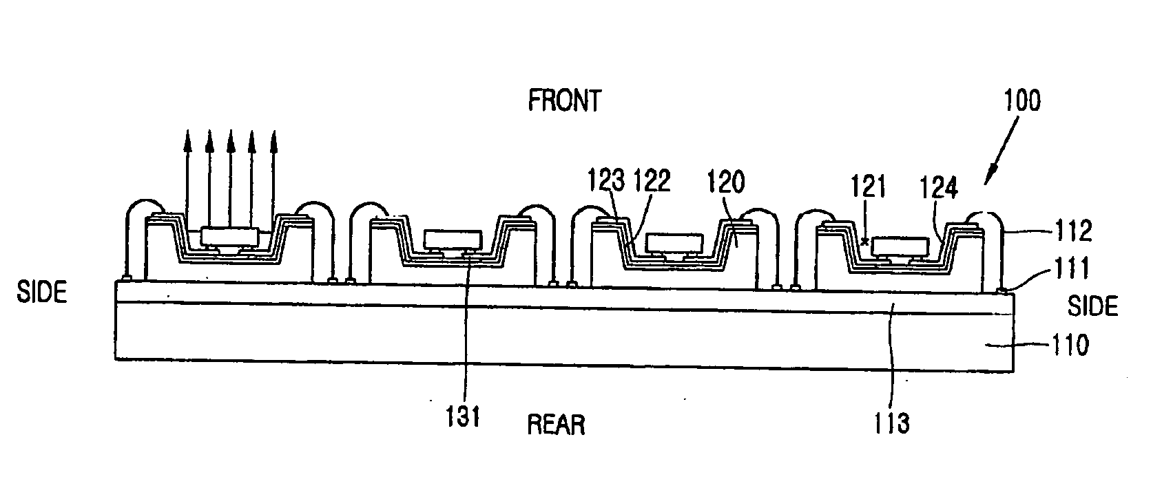
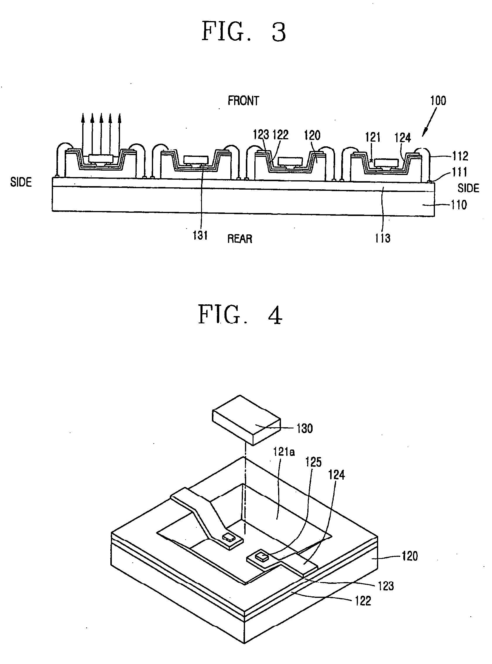
[0037]FIG. 3 is a longitudinal sectional view showing a light source apparatus in accordance with the present invention, FIG. 4 is an exploded perspective view showing a sub-mount and a light emitting device in the light source apparatus in accordance with the present invention, and FIG. 5 is a longitudinal sectional view showing the sub-mount and the light emitting device in the light source apparatus in accordance with the present invention.

[0038] As shown in FIGS. 3 to 5, a light source apparatus 100 in accordance with the present invention includes: a metal stem 110; a sub-mount 120 having one surface deposited over the metal stem 110 and ...


PUM


Abstract

A light source apparatus and a fabrication method thereof can prevent light interference between light emitting devices adjacent to each other and increase the luminous efficiency by collecting light emitted from the side of the light emitting device toward the front of a metal stem by forming grooves at a sub-mounts, bonding the light emitting device to the inside of the groove by a flip chip bonding method and forming a reflective layer inside the groove.

Description

BACKGROUND OF THE INVENTION [0001] 1. Field of the Invention [0002] The present invention relates to a light source apparatus and a fabrication method thereof, and more particularly, to a light source apparatus and a fabrication method thereof enabling light emitted from respective light emitting devices to be collected toward the front of a metal stem without loss of light. [0003] 2. Description of the Background Art [0004] A light emitting device which is actively being used at the moment is typically divided into a laser diode (LD) and a light emitting diode (LED). [0005] The LD is widely used as a light source in the field of optical communication, and has lately been used as an important component in the field of optical media such as a DVD player, a laser disc (LD) player, a mini disc (MD) player, or the like as well as in the filed of a compact disc (CD) player and a compact disc rewritable (CD-RW) player. [0006] In addition, the LED is widely used in a backlight unit (BLU), ...

Claims


Application Information

Patent Timeline
Patent Type & Authority Applications(United States)
IPC IPC(8): H01L29/06
CPCH01L33/486H01L33/62H01L33/64H05K1/053H05K3/328H05K2201/10106H05K2203/049H01L2224/48145H01L2224/48091H01L2924/00014H01L2924/00012
Inventor KIM, GEUN-HOSONG, KI-CHANG
Owner LG ELECTRONICS INC
Why Eureka
Try Eureka