Traction assembly for a vehicle
- Summary
- Abstract
- Description
- Claims
- Application Information
AI Technical Summary
Benefits of technology
Problems solved by technology
Method used
Image

Examples
Embodiment Construction
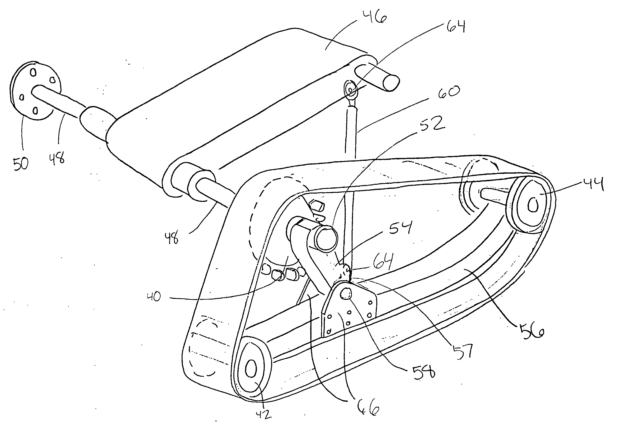
[0042] The present invention relates to a traction assembly for a vehicle using an endless traction band and a plurality of wheels for propulsion on irregular terrains.
[0043] The following description will be made according to embodiments of the present invention designed to be installed on ATVs and other similar vehicles. However, it is to be understood by the skilled addressee that the present invention can be adapted for any wheeled vehicles. Therefore, variants of the present invention adapted to be used on trucks, tractors and other similar vehicles fall inside the scope of the present invention.
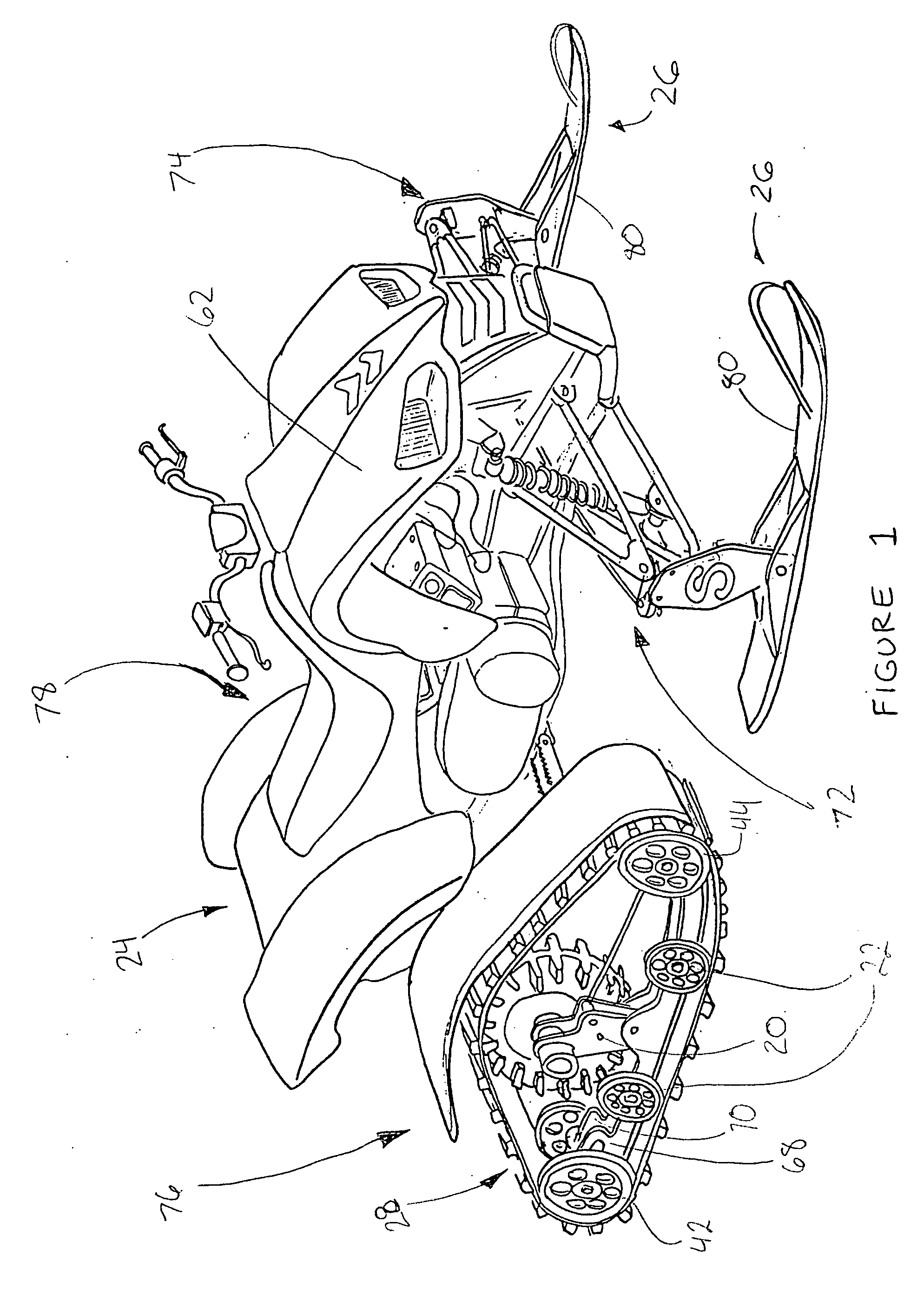
[0044] As seen in FIG. 1, the vehicle 24 is an ATV for which the regular wheels (not shown) are replaced with such traction assemblies 20 and ski assemblies 26. Such traction assemblies 20 can also replace the front wheels of a vehicle as shown in FIG. 5. Other vehicles designed to ride on irregular, snowy, sandy, muddy or softer terrains can also incorporate the use of traction assem...
PUM
 Abstract
Description
Claims
Application Information
 - Generate Ideas
- Intellectual Property
- Life Sciences
- Materials
- Tech Scout
- Unparalleled Data Quality
- Higher Quality Content
- 60% Fewer Hallucinations
Browse by: Latest US Patents, China's latest patents, Technical Efficacy Thesaurus, Application Domain, Technology Topic, Popular Technical Reports.
© 2025 PatSnap. All rights reserved.Legal|Privacy policy|Modern Slavery Act Transparency Statement|Sitemap|About US| Contact US: help@patsnap.com