Method and apparatus for attachment of a cover for a dynamoelectric machine

a technology for dynamoelectric machines and covers, applied in the field of covers for dynamoelectric machines, can solve the problems of plastic snaps being prone to creep, loose covers, and creating a rattl

Active Publication Date: 2006-08-17
BORGWARNER INC
View PDF6 Cites 21 Cited by
  • Summary
  • Abstract
  • Description
  • Claims
  • Application Information

AI Technical Summary

Benefits of technology

[0010] In another embodiment, a method to attach a protective cover to a wound-field electrical machine is disclosed. The method includes forming a one-piece cover attached to an end frame supporting at least one electrical component to protect the electrical component from external damage, the cover having an end wall and an axially extending side wall, the side wall having an end surface that engages the end frame; disposing a mounting boss at the end frame; extending a single fastener through the end surface; and securely holding the cover relative to the end frame via a clamp load at the single fastener.

Problems solved by technology

However, on extreme vibration applications, such as on a diesel engine, or with applications that must operate for an extended time, the plastic snaps are prone to creep, which leads to a loose cover.
The loose cover may create a rattle noise, and if severe enough, may even fall off after wearing the latch / frame interface.
This method overcomes the creep issue, but it also adds material and assembly costs.

Method used


Image

  • Method and apparatus for attachment of a cover for a dynamoelectric machine
  • Method and apparatus for attachment of a cover for a dynamoelectric machine
  • Method and apparatus for attachment of a cover for a dynamoelectric machine

Examples


Embodiment Construction

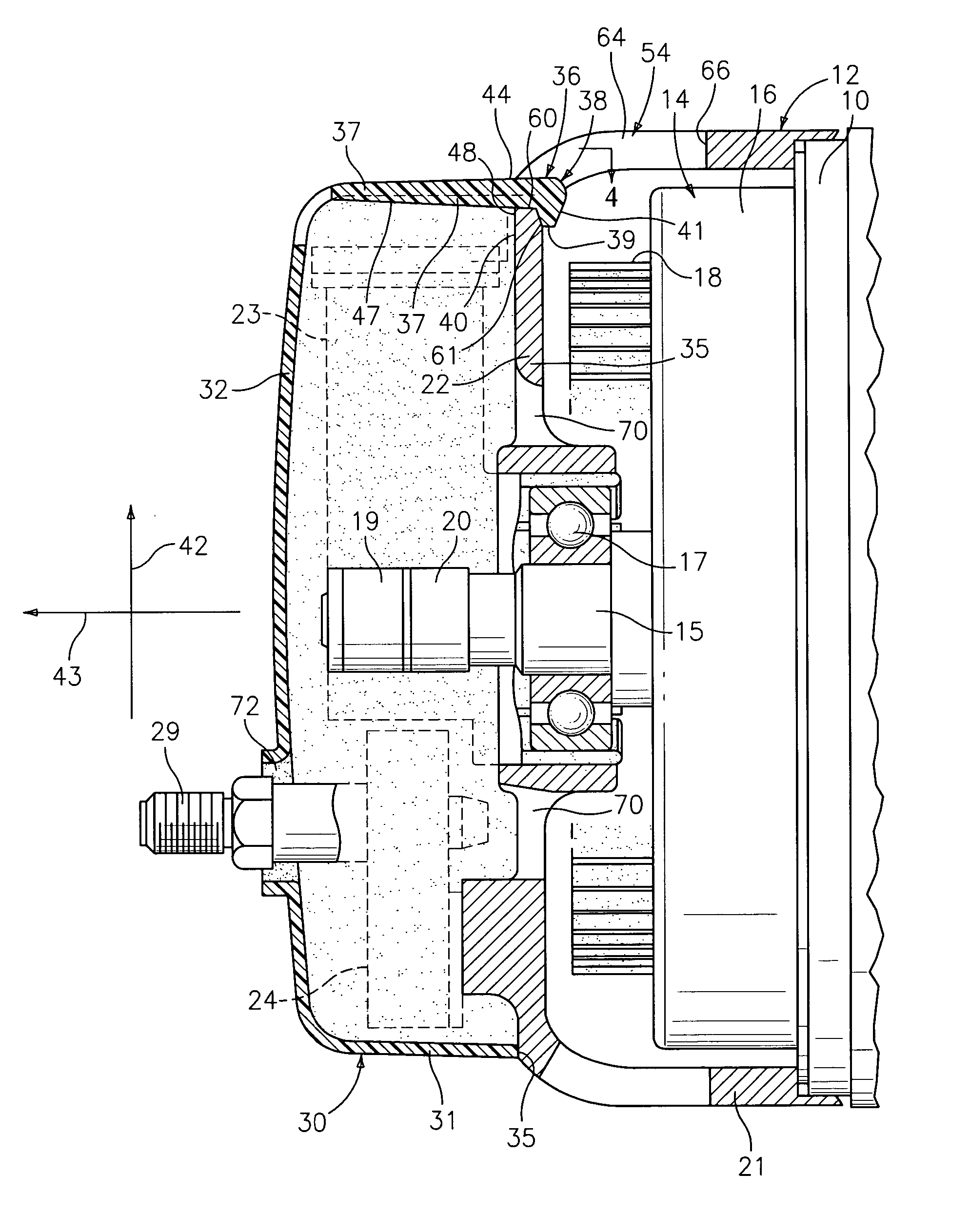
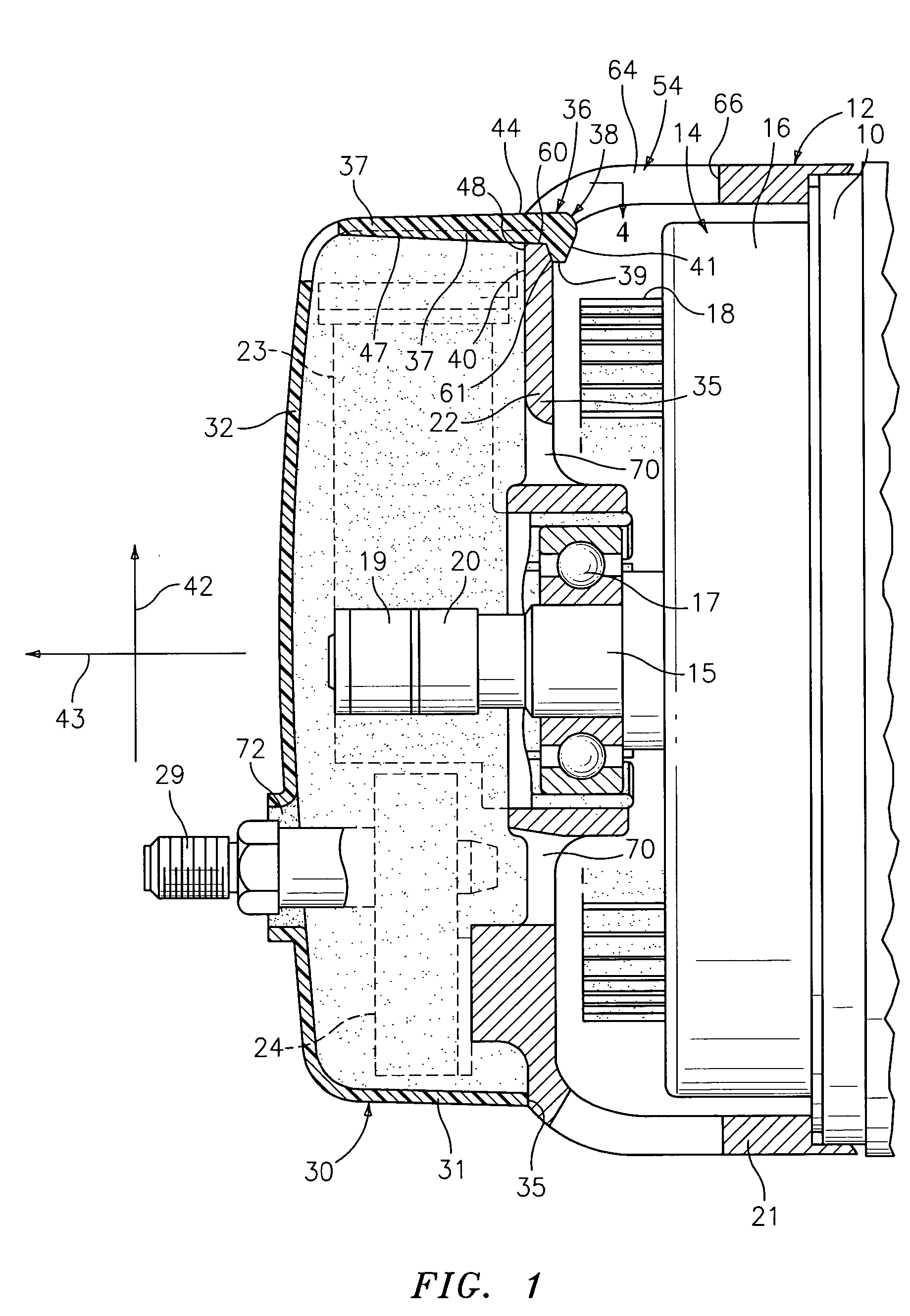
[0017] Referring now to the drawings, and more particularly to FIG. 1, a cover is shown attached to one end of a dynamoelectric machine. The dynamoelectric machine is an alternating current generator for vehicle use.

[0018] The alternating current generator has a stator assembly that is shown diagrammatically in FIG. 1 and designated as 10. This stator assembly, as is well known to those skilled in the art, comprises a slotted stator core. This core supports a three-phase stator winding. The stator assembly is supported by a slip ring end frame 12 and a drive end frame which is not illustrated. The end frame 12 is formed of a metallic material such as die cast aluminum.

[0019] The generator has a rotor that is shown partly diagrammatically in FIG. 1 and designated as 14. The rotor 14 has a rotor shaft 15 that carries pole members having interleaved pole teeth, a rotor core and a field coil disposed about the rotor core. The just described parts are not shown in detail but are shown ...


PUM


Abstract

A cover assembly for one end of a rotating electrical machine includes a one-piece cover formed of plastic material attached to an end frame supporting at least one electrical component to protect said electrical component from external damage, the cover has an end wall and an axially extending side wall, the side wall has an end surface that engages the end frame; a mounting boss is disposed at the end frame; and a single fastener extends through the end surface. A clamp load at the single fastener securely holds the cover relative to the end frame.

Description

TECHNICAL FIELD [0001] This application relates generally to a cover for dynamoelectric machines such as alternating current generators and, more particularly, to a cover that is attached to an end frame of a dynamoelectric machine with a single fastener to provide protection from external damage for electrical components mounted on the end frame. BACKGROUND [0002] Rotating electrical machines such as vehicle alternators (dynamoelectric machines) (also commonly referred to as “generators”) having a stator secured within the housing of the machine and a rotor assembly that extends axially through the motor or generator are well known. The housing often includes two or more spaced apart frames which provide the main structural elements of the alternator. The frame closest to a pulley, which powers the alternator via a belt drive is commonly referred to as the drive end frame. The opposite frame is commonly referred to as the slip ring end frame. The frames support the rotor assembly c...

Claims


Application Information

Patent Timeline
Patent Type & Authority Applications(United States)
IPC IPC(8): H02K5/00H02K13/00H01R39/38G03B17/26
CPCH02K5/10H02K5/141H02K11/046H02K11/05
Inventor BRADFIELD, MICHAEL D.MCCORD, MICHAEL A.
Owner BORGWARNER INC
Why Eureka
Try Eureka