UWB antenna having 270 degree coverage and system thereof

a technology of 270 degree coverage and antenna, which is applied in the direction of independent non-interfering antenna combinations, building scaffolds, building aids, etc., can solve the problems of many of these antennas producing resonances, low level, and generation of null areas, so as to achieve the effect of minimizing the null area

Active Publication Date: 2006-08-17
SAMSUNG ELECTRONICS CO LTD
View PDF2 Cites 14 Cited by
  • Summary
  • Abstract
  • Description
  • Claims
  • Application Information

AI Technical Summary

Benefits of technology

[0011] Accordingly, the present invention has been made to solve the above-mentioned problems, and an aspect of the present inv

Problems solved by technology

However, many of these antennas produce resonances only when operating in a band of only several percentages.
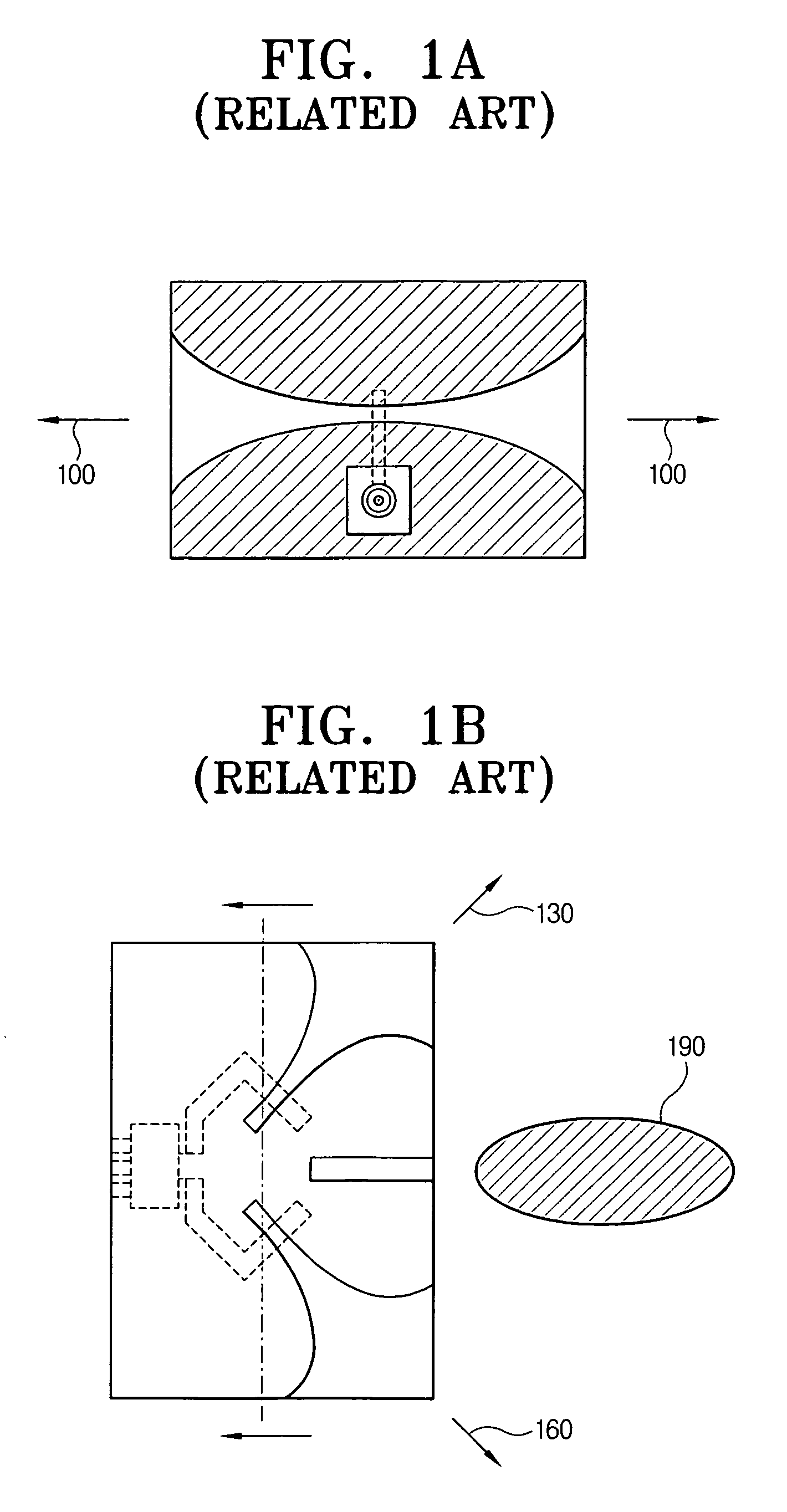
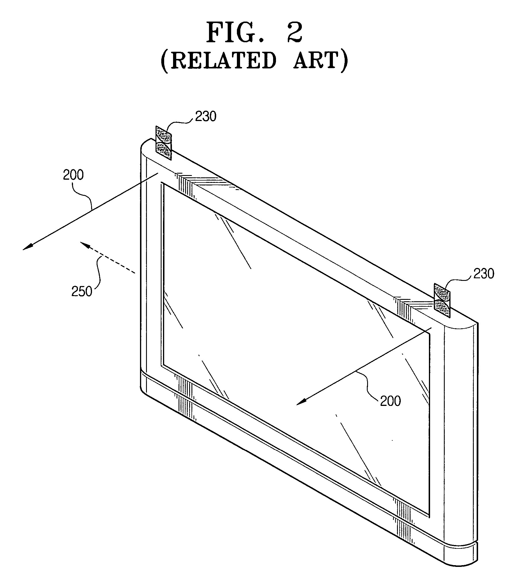
However, in a case where such a planar type UWB antenna is mounted in a digital TV or a settop box, a null area is generated due to a reduction

Method used


Image

  • UWB antenna having 270 degree coverage and system thereof
  • UWB antenna having 270 degree coverage and system thereof
  • UWB antenna having 270 degree coverage and system thereof

Examples


Embodiment Construction

[0025] Exemplary embodiments of the present invention will be described in greater detail with reference to the accompanying drawings.

[0026] In the following description, same drawing reference numerals are used for the same elements even in different drawings. The matters defined in the description such as a detailed construction and elements are provided to assist in a comprehensive understanding of the invention. Thus, it is apparent that the present invention can be carried out without those defined matters. Also, well-known functions or constructions are not described in detail since they would obscure the invention in unnecessary detail.

[0027]FIG. 3A is a schematic view illustrating an experiment for measuring packet error rates with respect to an existing planar type UWB antenna and measured values. Referring to FIG. 3A, a planar type UWB antenna 300, a connector 310, and a UWB transmitter 320 are used to measure packet error rates with respect to the planar type UWB antenn...


PUM


Abstract

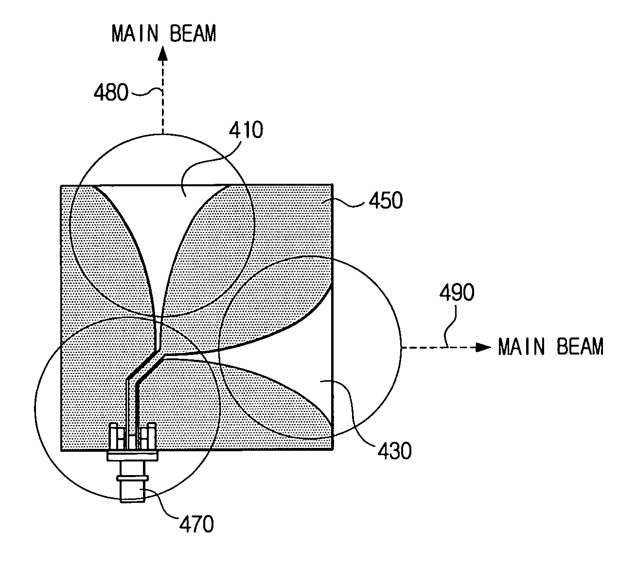
An ultra wide band antenna having a 270° coverage and a system thereof. The ultra wide band antenna includes a dielectric substrate, two Vivaldi horn radiators attached to the dielectric substrate and including central axes orthogonal to each other, and a single radiator coupled to the two Vivaldi horn radiators. The ultra wide band antenna system includes: a first ultra wide band antenna including a dielectric substrate, two Vivaldi horn radiators attached to the dielectric substrate and including central axes orthogonal to each other, and a single radiator coupled to the two Vivaldi horn radiators; and a second ultra wide band antenna including a dielectric substrate, two Vivaldi horn radiators attached to the dielectric substrate and including central axes orthogonal to each other, and a single radiator coupled to the two Vivaldi horn radiators, positioned on an identical plane to the first ultra wide band antenna, and forming a line symmetric structure together with the first ultra wide band antenna.

Description

CROSS-REFERENCE TO RELATED APPLICATIONS [0001] This application claims priority from Korean Patent Application No. 10-2005-0012380 filed Feb. 15, 2005, in the Korean Intellectual Property Office, the disclosure of which is incorporated herein by reference in its entirety. BACKGROUND OF THE INVENTION [0002] 1. Field of the Invention [0003] Apparatuses and methods consistent with the present invention relate to an ultra wide band (UWB) antenna and a system thereof, and more particularly, to a UWB antenna having a 270° coverage and a system thereof. [0004] 2. Description of the Related Art [0005] The use of antennas in cellular phones, radios, televisions, computer networks, and the like has been generalized. Antennas are systems including conductors used for transmitting and receiving radio waves or other electromagnetic waves by wire. [0006] However, many of these antennas produce resonances only when operating in a band of only several percentages. Such a narrow band width antenna m...

Claims


Application Information

Patent Timeline
IPC IPC(8): H01Q13/10
CPCH01Q13/085H01Q21/28E04G1/15E04G1/152E04G21/32E04G2001/157
Inventor KIM, YONG-JINKWON, DO-HOONKIM, YOUNG-EILLEE, SEONG-SOO
Owner SAMSUNG ELECTRONICS CO LTD
Why Eureka
Try Eureka