Liquid crystal display apparatus

a technology of liquid crystal display and display apparatus, which is applied in the direction of instruments, optics, cooling/ventilation/heating modification, etc., can solve the problems of heat loss, heat may affect the components, and the heat release plate cannot fully transport the heat to the back of the display apparatus

Inactive Publication Date: 2006-08-17
DENSO CORP
View PDF5 Cites 36 Cited by
  • Summary
  • Abstract
  • Description
  • Claims
  • Application Information

AI Technical Summary

Benefits of technology

[0010] In view of the above described problem, it is an object of the present invention to provide a liquid crystal display (LCD) apparatus in which heat generated by a drive circuit is prevented from being transferred to a component disposed near the drive circuit.
[0013] Thus, the heat transport member prevents the heat from being transferred to components such as the light guide plate and the liquid crystal drive circuit of the circuit board, which are susceptible to heat and disposed near the light source drive circuit or the light source. In the LCD apparatus, therefore, it is possible to prevent the heat from causing problems such as deformation of the light guide plate and a wrong display appearing on the liquid crystal member.

Problems solved by technology

If the generated heat is transferred to components deposed near the LED drive circuit, the heat may affect the components.
Therefore, a large portion of the heat generated by the LED drive circuit is released near the LED drive circuit and affects the components disposed near the LED drive circuit.
In the display apparatus, although the heat release plate extends to the back of the display apparatus, the heat release plate cannot fully transport the heat to the back of the display apparatus due to the high heat resistance and the wide shape.
Consequently, the components disposed near the LED drive circuit may be subjected to high temperature.

Method used


Image

  • Liquid crystal display apparatus
  • Liquid crystal display apparatus
  • Liquid crystal display apparatus

Examples


first embodiment

[0038] A LCD apparatus 100 of the first embodiment will be now described with reference to FIGS. 1 to 4. The LCD apparatus 100 may be, for example, used as a display apparatus for a navigation system or an indicator such as a speed meter and a tachometer arranged in an instrument panel of a vehicle.

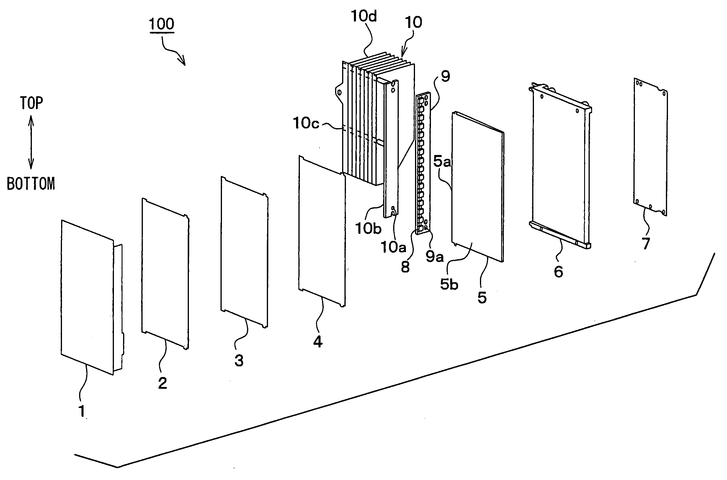
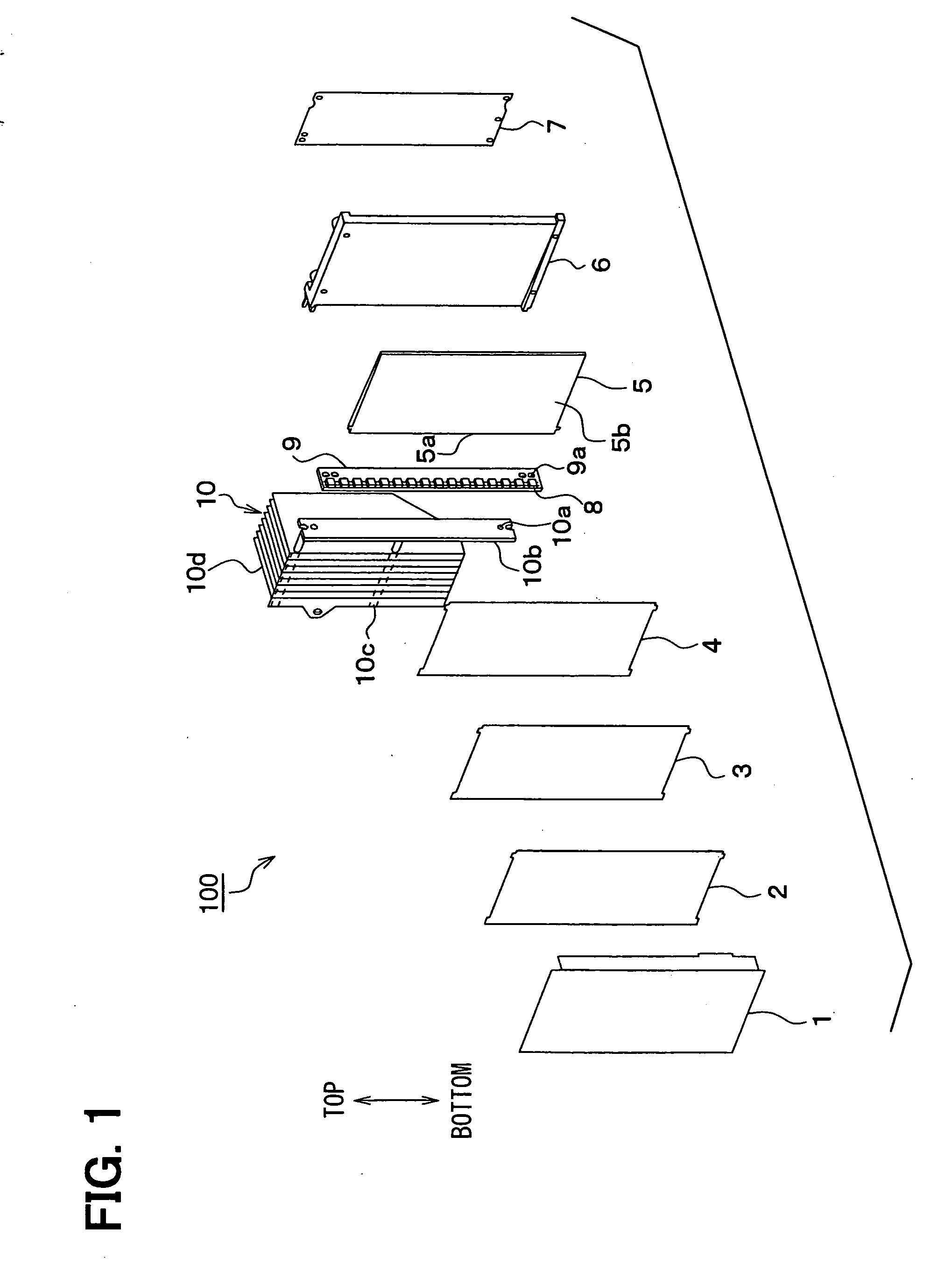
[0039] As shown in FIG. 1, the LCD apparatus 100 includes a liquid crystal panel 1, optical sheets 2, 3, a diffusion sheet 4, a light guide panel 5, a reflector panel 6, a circuit board 7, a light emitting diode (LED) 8, a LED drive circuit 9, and a cooling module 10.

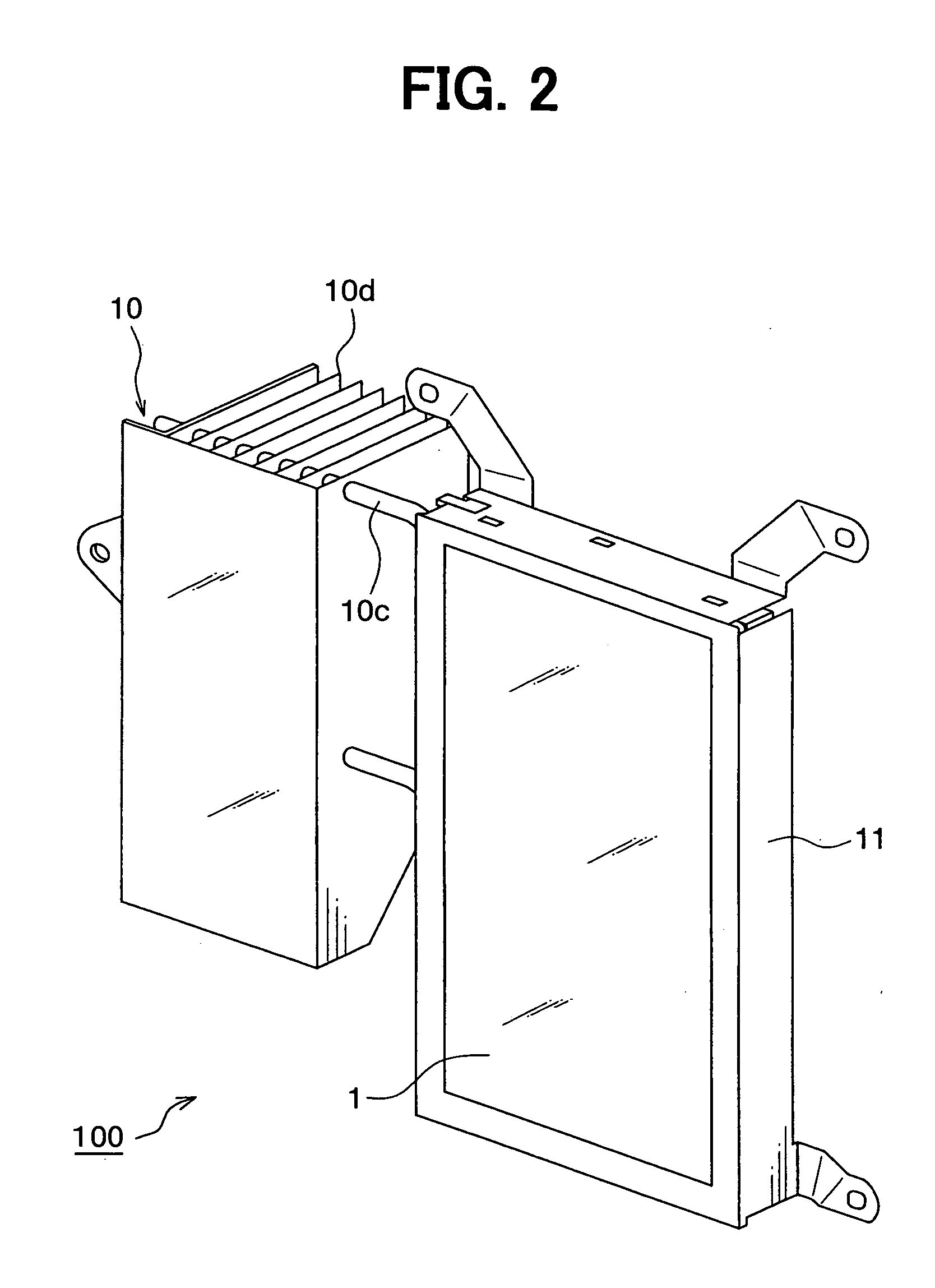
[0040] The liquid crystal panel 1 is a well-known thin film transistor (TFT) liquid crystal panel. The optical sheets 2, 3, the diffusion sheet 4, the light guide panel 5, the reflector panel 6, and the circuit board 7 are disposed in this order behind the liquid crystal panel 1 and held in a cover 11 shown in FIG. 2.

[0041] The optical sheets 2, 3 are laminated into single sheet. The single sheet reflects light entering th...

second embodiment

[0067] A LCD apparatus 200 of the second embodiment will be now described with reference to FIGS. 5 to 8.

[0068] The LCD apparatus 200 has a structure basically similar to that of the LCD apparatus 100 according to the first embodiment. In the LCD apparatus 200, as shown in FIG. 6A, the LED drive circuit 9 is disposed on the bottom side of the LCD apparatus 200. The heat pipe 10c has one end portion joined to the LED drive circuit 9 through the attachment plate 10b and the other end portion extending to the heat release unit 10d. The heat pipe 10c is bent upwardly at a bent portion 10ca so that the other end portion of the heat pipe 10c is positioned behind the circuit board 7. Accordingly, the heat release unit 10d is disposed behind the circuit board 7.

[0069] Thus, the heat pipe 10c is disposed on the back side of the LCD apparatus 200 so that the heat release unit 10d can be disposed on the back side of the LCD apparatus 200. Even when the heat pipe 10c and the heat release unit...

third embodiment

[0076] A LCD apparatus 400 of the third embodiment will be now described with reference to FIG. 10.

[0077] The LCD apparatus 400 has a structure basically similar to that of the LCD apparatus 100 according to the first embodiment. In the LCD apparatus 400, a light permeable panel 20 is disposed instead of the light guide panel 5, and the LED drive circuit 9 is disposed behind the light permeable panel 20. The LED 8 is mounted on one surface of the aluminum substrate of the LED drive circuit 9 to face the light permeable panel 20.

[0078] The light permeable panel 20 acts as the light waveguide path. Light emitted by the LED 8 is emitted to the liquid crystal panel 1 after passing through the light permeable panel 20. Therefore, the display appears on the liquid crystal panel 1.

[0079] In the LCD apparatus 400, the heat pipe 10c has one end portion disposed along the back surface of the LED drive circuit 9 and the other end portion projecting horizontally from the LED drive circuit 9 ...


PUM

PropertyMeasurementUnit
incident angleaaaaaaaaaa
heat conductivityaaaaaaaaaa
heataaaaaaaaaa

Abstract

A liquid crystal display apparatus includes a light source, a light source drive circuit for switching the light source on and off, a heat release member for releasing heat generated by at least one of the light source drive circuit and the light source, and a heat transport member for transporting the heat to the heat release member. The light source drive circuit is connected to the heat release member through the heat transport member. The heat transport member has high heat conductivity so that a large part of the heat can be transferred to the heat release member through the heat transport member for a short time. Thus, the heat transport member prevents the heat from affecting components disposed near the light source drive circuit or the light source.

Description

CROSS REFERENCE TO RELATED APPLICATION [0001] This application is based on Japanese Patent Applications No. 2005-37642 filed on Feb. 15, 2005, No. 2005-37643 filed on Feb. 15, 2005, and No. 2005-37644 filed on Feb. 15, 2005, the disclosures of which are incorporated herein by reference. FIELD OF THE INVENTION [0002] The present invention relates to a liquid crystal display apparatus for performing a display, which is suitably used for a vehicle, for example. BACKGROUND OF THE INVENTION [0003]FIG. 20 is a cross-sectional view showing a liquid crystal display (LCD) apparatus disclosed in JP-A-2004-279262. The LCD apparatus includes a liquid crystal display member J1, an optical member J2 (e.g., an optical sheet and a diffusion sheet) disposed behind the liquid crystal display member J1, a light-emitting diode (LED) J3 as a light source element, a circuit board J4 having a LED drive circuit, a LED control circuit and a liquid crystal drive circuit, a light guide plate J5 as a light wav...

Claims


Application Information

Patent Timeline
Patent Type & Authority Applications(United States)
IPC IPC(8): G02F1/1333
CPCG02F1/133308G02F1/133385G02F1/133615G02F2001/133628G02F1/133628H05K7/2099
Inventor KUROKAWA, KAZUMASAKONDO, YOSHIMISHIBATA, HIROKAZU
Owner DENSO CORP
Why Eureka
Try Eureka