Alignment mode selection mechanism for elastic interface

a technology of elastic interface and selection mode, which is applied in the direction of generating/distributing signals, digital transmission, instruments, etc., can solve the problems of jitter and other forms of distortion, the speed of the interface between chips (bus cycle time) becomes a limiting constraint, and the delay of data signals can require extensive administrative overhead and additional circuitry

Inactive Publication Date: 2006-08-17
IBM CORP
View PDF2 Cites 10 Cited by
  • Summary
  • Abstract
  • Description
  • Claims
  • Application Information

AI Technical Summary

Benefits of technology

[0007] The present invention provides methods and apparatuses that enable choosing from among more than one alignment mode in elastic interface systems. In a first embodiment, a method is provided for receiving a transmission of digital data in an elastic interface system. A clock/data group is received on a bus. The clock/data group has a clock signal having a plurality of clock edges. The clock/data group also has a plurality of data bits that have a plurality of even data beats and a plurality of odd data beats. The plurality of data bits are launched substantially simultaneously. The plurality of data bits have per-bit skew upon receiving, with a latest data bit. Each of the plurality of received data bits is delayed individua...

Problems solved by technology

As CPU speeds increase, the speed of the interface between chips (bus cycle time) becomes a limiting constraint because latencies across the interfaces may exceed the system clock period.
While it is necessary to align the individual data bits within a clock/data group at the receiving end, such delays can cause jitter and other forms of distortion.
In addition to causing jitter and distortion, delaying data signals can r...

Method used


Image

  • Alignment mode selection mechanism for elastic interface
  • Alignment mode selection mechanism for elastic interface
  • Alignment mode selection mechanism for elastic interface

Examples


Embodiment Construction

[0033] In the following description, numerous specific details are set forth such as specific data bit lengths, ranges of delay times, and interface alignment patterns, to provide a thorough understanding of the present invention. However, it will be obvious to those skilled in the art that the present invention may be practiced without such specific details. In other instances, well-known circuits have been shown in block diagram form in order not to obscure the present invention in unnecessary detail. Some details concerning timing considerations, detection logic, and the like have been omitted inasmuch as such details are not necessary to obtain a complete understanding of the present invention and are within the skills of persons of ordinary skill in the relevant art. Refer now to the drawings wherein depicted elements are not necessarily shown to scale and like or similar elements may be designated by the same reference numeral through the several views.

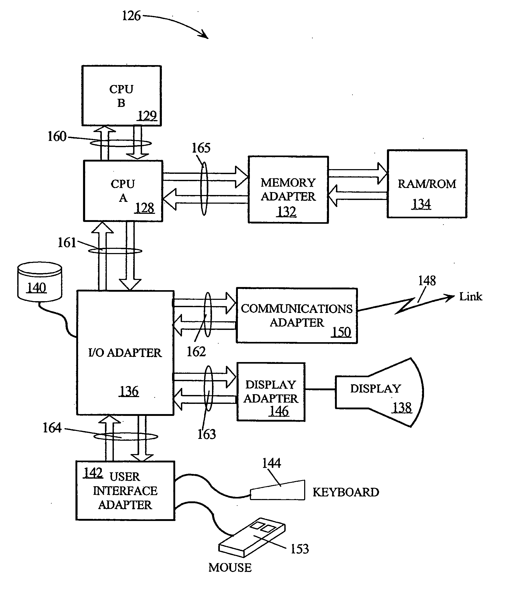
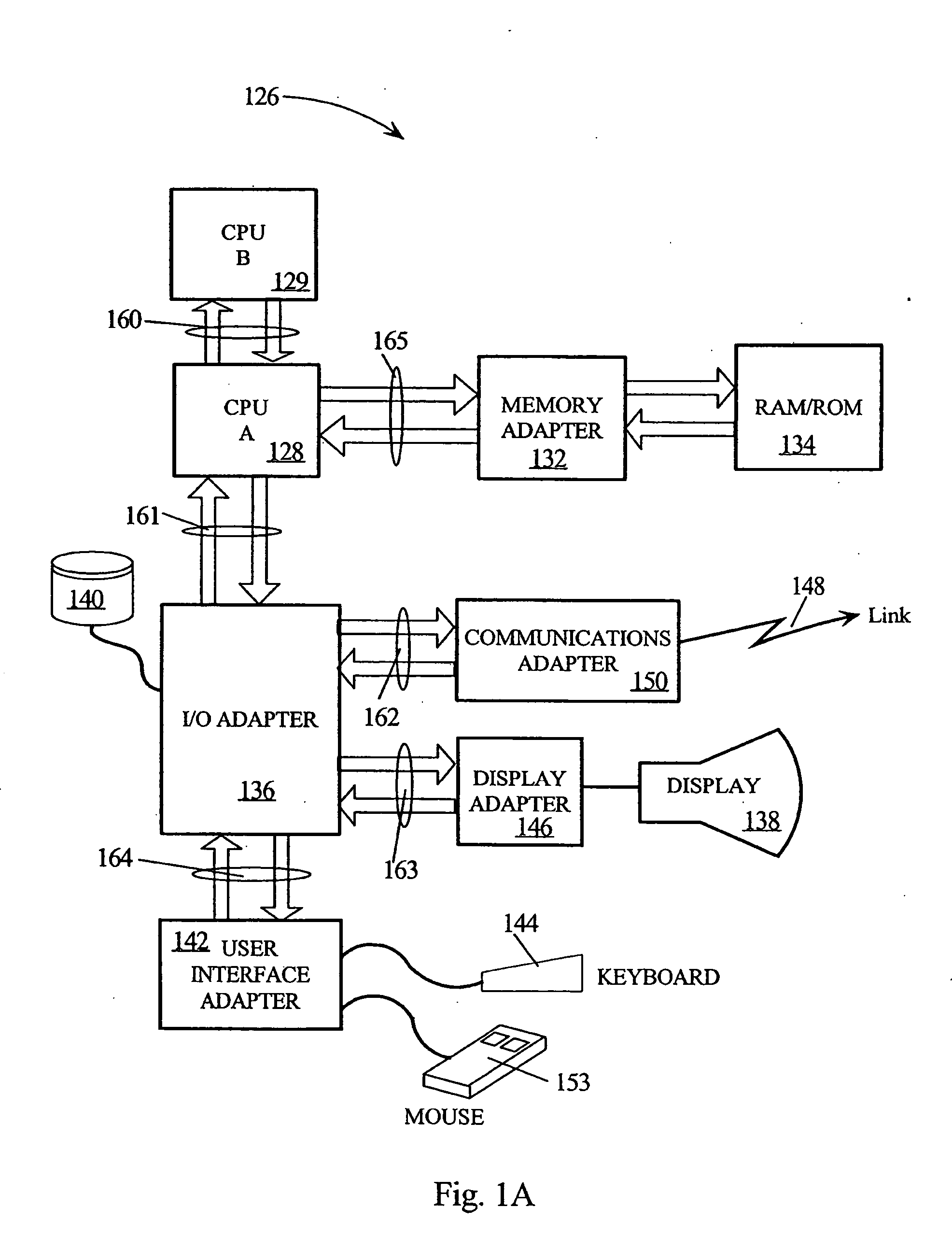
[0034]FIG. 1A is a high...


PUM


Abstract

Methods and apparatus are disclosed for aligning received data bits in elastic interface systems. Depending upon which one of several alignment modes is selected, data bits can be loaded into FIFO latches on rising clock edges if the data was sent on rising clock edges, on falling clock edges if the data was sent on falling clock edges, or on the nearest clock edge if minimum latency is desired. Alternatively, data bits can be delayed by one or more bit times before loading into FIFO latches to reduce the elastic interface system's sensitivity to drift. The present invention permits a user to trade off factors related to for latency, drift, and skew by choosing among different alignment modes in an elastic interface system.

Description

TECHNICAL FIELD [0001] The present invention relates in general to data processing systems, and in particular, to mechanisms for communicating data between integrated circuits. BACKGROUND INFORMATION [0002] Modern data processing systems require the rapid transfer of data between integrated circuits (“chips”). For example, a central processing unit (CPU) transfers data to the memory system, which may include a memory controller and off-chip cache. In a multi-CPU system, data may be transferred between CPUs. As CPU speeds increase, the speed of the interface between chips (bus cycle time) becomes a limiting constraint because latencies across the interfaces may exceed the system clock period. [0003] When data is launched from one chip to another chip, it can be launched simultaneously within numerous clock / data groups. Each clock / data group consists of multiple data bits and a clock signal, each of which travels over an individual conductor. Due to process variations and varying cond...

Claims


Application Information

Patent Timeline
IPC IPC(8): G11C19/00
CPCG06F5/10G06F2205/104G11C19/287
Inventor FERRAIOLO, FRANK D.PETERSON, GARY A.REESE, ROBERT J.
Owner IBM CORP
Why Eureka
Try Eureka