Distribution line carrier transmitting device

a transmission device and transmission line technology, applied in the direction of digital transmission, secret communication, electrical equipment, etc., can solve the problems of difficult one-by-one transmission of installed equipment and filter exchange, and achieve the effect of eliminating the influence of noise and stable communication

Inactive Publication Date: 2006-08-17
MITSUBISHI ELECTRIC CORP
View PDF0 Cites 0 Cited by
  • Summary
  • Abstract
  • Description
  • Claims
  • Application Information

AI Technical Summary

Benefits of technology

[0011] The invention has been made to solve the problems as described above, and has an object to provide a distribution line carrier transmitting device in which even if a frequency band used for communication is variable, a filter to be used is changed according to the frequency band, so that an influence of noise is eliminated, and stable communication is enabled.

Problems solved by technology

However, the installation place of this device is the vicinity of a transformer installed on an electric pole or the vicinity of a transformer buried in the ground, that is, the device is installed at a place where a filter can not be easily changed, and it is difficult to exchange the filter one by one for the installed equipment.

Method used


Image

  • Distribution line carrier transmitting device
  • Distribution line carrier transmitting device
  • Distribution line carrier transmitting device

Examples


embodiment 1

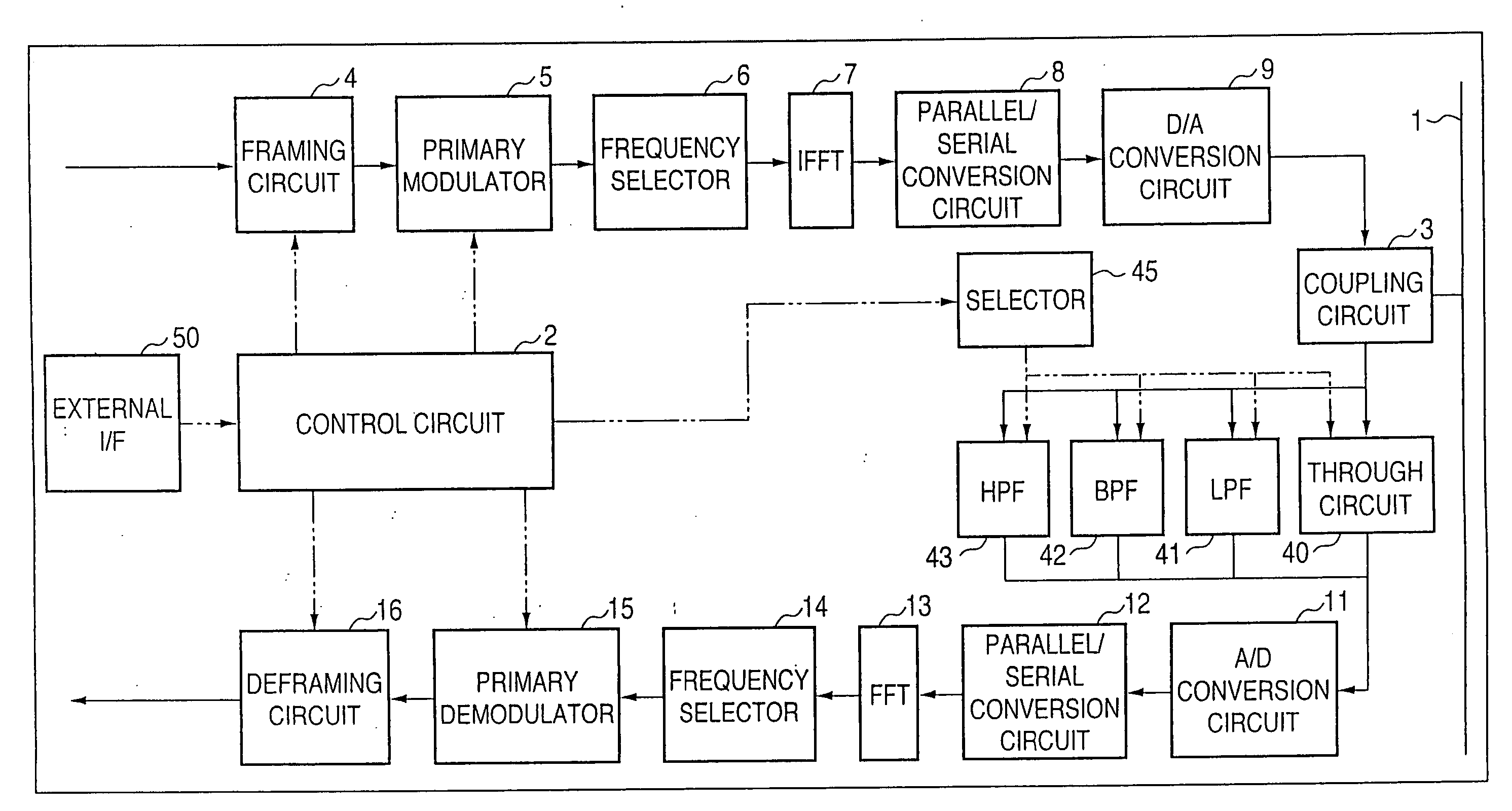
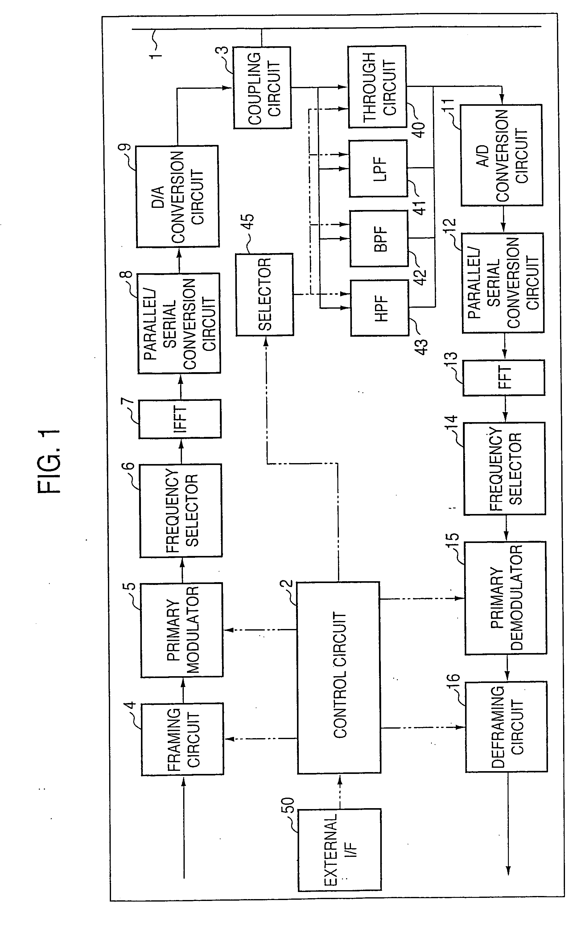
[0026] Hereinafter, embodiment 1 of the invention will be described with reference to FIG. 1.

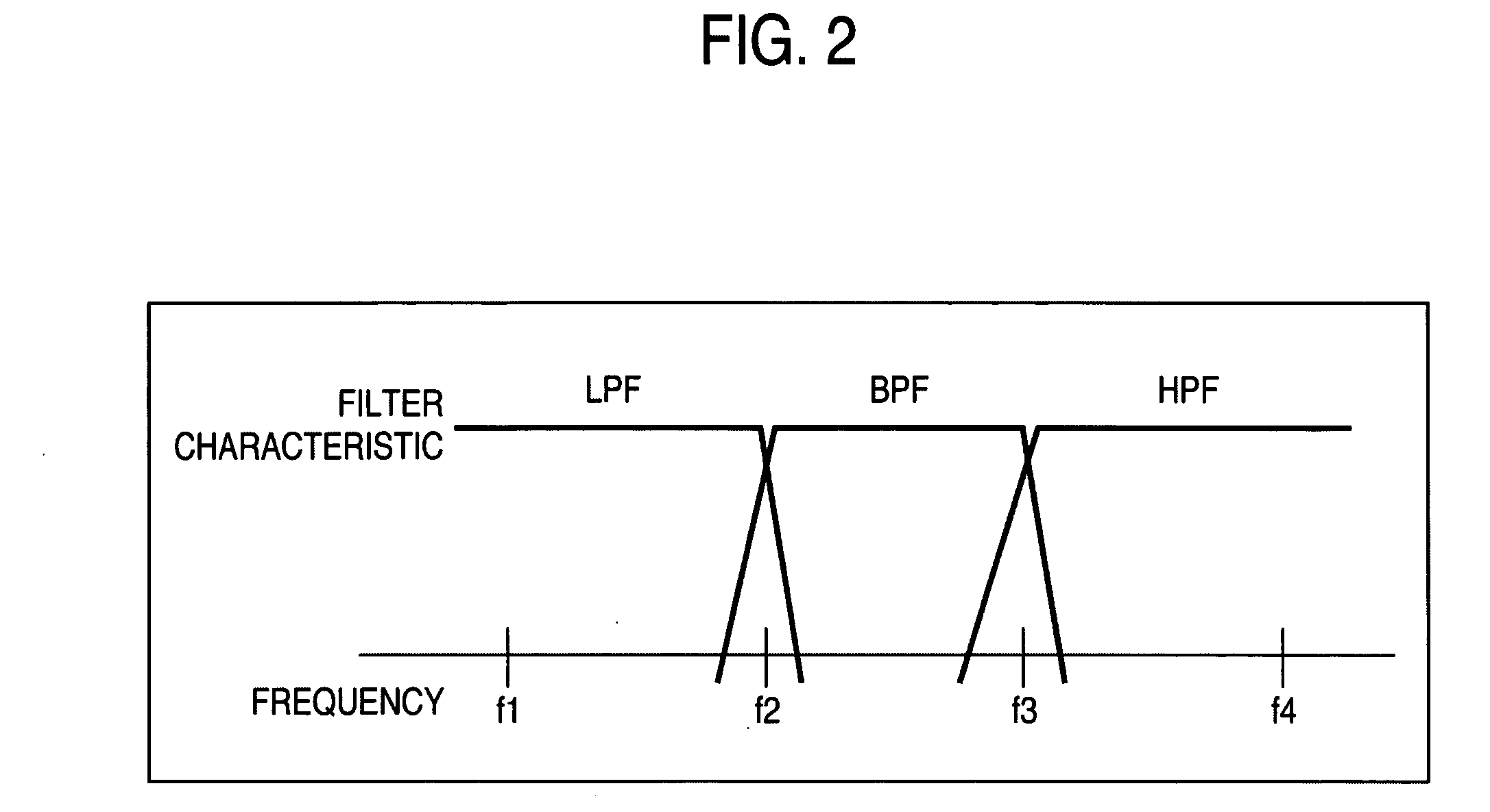
[0027] Reference numerals 1 to 16 denote the same parts as those in FIG. 11. Reference numeral 40 denotes a through circuit, the conduction / non-conduction of which can be controlled from the control circuit 2 and which has no filter function at the conduction and allows all frequencies to pass through as they are. Reference numeral 41 denotes a low pass filter (LPF) which reduces a voltage on the high band side outside a use voltage in the case where the lowest band is used in the distribution line carrier transmission; 42, a band pass filter (BPF) which reduces a voltage on the low band side and high band side outside a use band in the case where an intermediate band is used in the distribution line carrier transmission; 43, a high pass filter (HPF) which reduces a voltage on the low band side outside a use band in the case where the highest frequency band is used in the distribution line ...

embodiment 2

[0031] In embodiment 1, although the switching of the filter is realized using the distribution line communication, even in a method of using the same distribution line communication, as shown in FIG. 4, there is a method in which a band different from a normal communication band is prepared for filter control. In this embodiment, an external I / F 50 is a distribution line communication I / F, and as shown in FIG. 5, a band pass filter 51 dedicated for a filter control signal and a demodulation circuit 52 dedicated for a filter control signal are provided to branch from a coupling circuit 3, and when a band of from f1 to f2 is a normal communication band, communication dedicated for filter control is performed using a band, like a band of from f3 to f4, different from the band of from f1 to f2.

[0032] In this embodiment, in the case where a filter control signal is received, the signal is processed by the circuit dedicated for the filter control signal, that is, the band pass filter 51...

embodiment 3

[0033] In embodiment 1, although one of the low pass filter, the band pass filter, the high pass filter and the through circuit is selected according to the band used for the communication, there is a method in which as a filter, a high pass filter and a low pass filter are combined in a multi-stage configuration. Embodiment 3 using this method will be described with reference to FIG. 6. Reference numerals 61 to 63 denote low pass filters corresponding to different frequency bands; and 66 to 68, high pass filters corresponding to different frequency bands. Reference numerals 60 and 65 denote through circuits.

[0034] In this embodiment, a selector 45 is operated based on instructions from an external I / F 50, one kind is selected from the high pass filters 60 to 63, and one kind is selected from the low pass filters 65 to 68. By this, filters corresponding to sixteen kinds of bands can be realized from eight kinds of filters. That is, by this method, filters corresponding to frequency...


PUM


Abstract

There is provided a distribution line carrier transmitting device which supports, for example, frequency division communication and in which even a frequency band used for communication is variable, a filter to be used is changed according to the frequency band, so that an influence of noise is eliminated, and stable communication is enabled. The distribution line carrier transmitting device includes plural filters to selectively attenuate a signal in a band not used for the communication among received signals, and a selection unit to select a specified filter among the plural filters according to an instruction from an external I/F.

Description

BACKGROUND OF THE INVENTION [0001] 1. Field of the Invention [0002] The present invention relates to a distribution line carrier transmitting device which supports, for example, frequency division communication and in which a frequency band used for communication is variable. [0003] 2. Description of the Related Art [0004]FIG. 11 is a block diagram showing, in a conventional distribution line carrier transmitting device disclosed in, for example, patent document 1 (JP-A-2001-308755 (page 6, FIG. 1)), a use method of a filter to attenuate high-level noise which interferes with and disturbs communication. In FIG. 11, reference numeral 1 denotes a distribution line of commercial power source as a distribution line carrier transmission path; and 2, a control circuit which includes a microprocessor and controls respective parts of the transmitting device. Reference numeral 3 denotes a coupling circuit which allows a high frequency communication signal to pass through between the transmit...

Claims


Application Information

Patent Timeline
Patent Type & Authority Applications(United States)
IPC IPC(8): H04K1/10
CPCH04L5/06H04B3/56
Inventor MINATO, KEIICHIHORI, YASUAKI
Owner MITSUBISHI ELECTRIC CORP
Why Eureka
Try Eureka