
Wire network mapping method and apparatus using impulse responses

a technology of impulse response and wire network, applied in the field of electromechanical testing, can solve problems such as failure of system, aging wiring in buildings, consumer products, industrial machinery,

Active Publication Date: 2006-08-17
UNIV OF UTAH RES FOUND
View PDF2 Cites 44 Cited by
  • Summary
  • Abstract
  • Description
  • Claims
  • Application Information

AI Technical Summary

Benefits of technology

[0011] It has been recognized that it would be advantageous to develop a technique for mapping an unknown or partially unknown network topology.
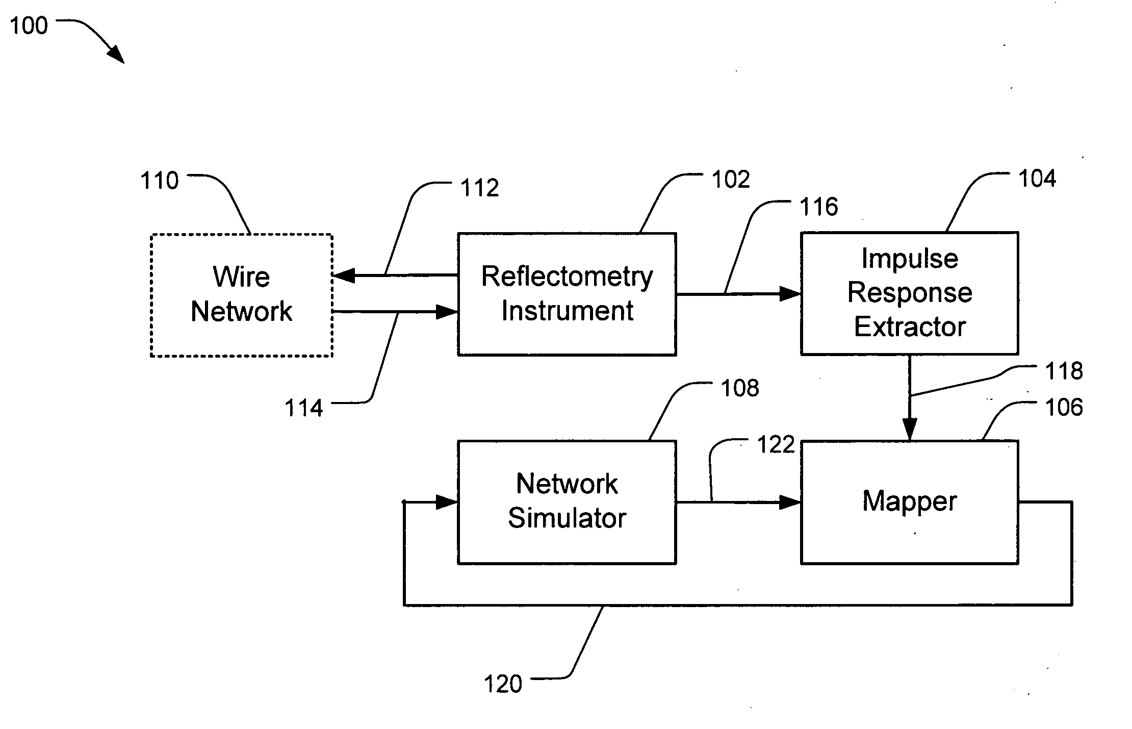
[0012] One embodiment of the invention is a method for mapping a wire network. A reflectometry response is obtained from the wire network, and an estimated impulse response is estimated from the reflectometry response. A wire network model is initialized and iteratively improved by simulating the impulse response of the wire network model and then adjusting the wire network model to reduce the differences between the hypothesized network topology and estimated impulse response.

Problems solved by technology

Failures in the wiring frequently result in failure of the system.
For example, aging wiring in buildings, aircraft and transportation systems, consumer products, industrial machinery, etc. is among the most significant potential causes of catastrophic failure and maintenance cost in these structures.
Impedance mismatches can be caused by a variety of things, including for example, breaks in the wire, short circuits, branches, and wire gauge changes.
Interpreting the results obtained with a reflectometry instrument for anything other than simple wires typically requires great expertise, as the reflectometry response can be very complex.
Mismatches also affect the signal passing past the mismatch.
For example, a pair of mismatches can result in an infinite, although decaying, train of reflections as a portion of the test signal bounces back and forth.
Testing of networks of wires has proven challenging.
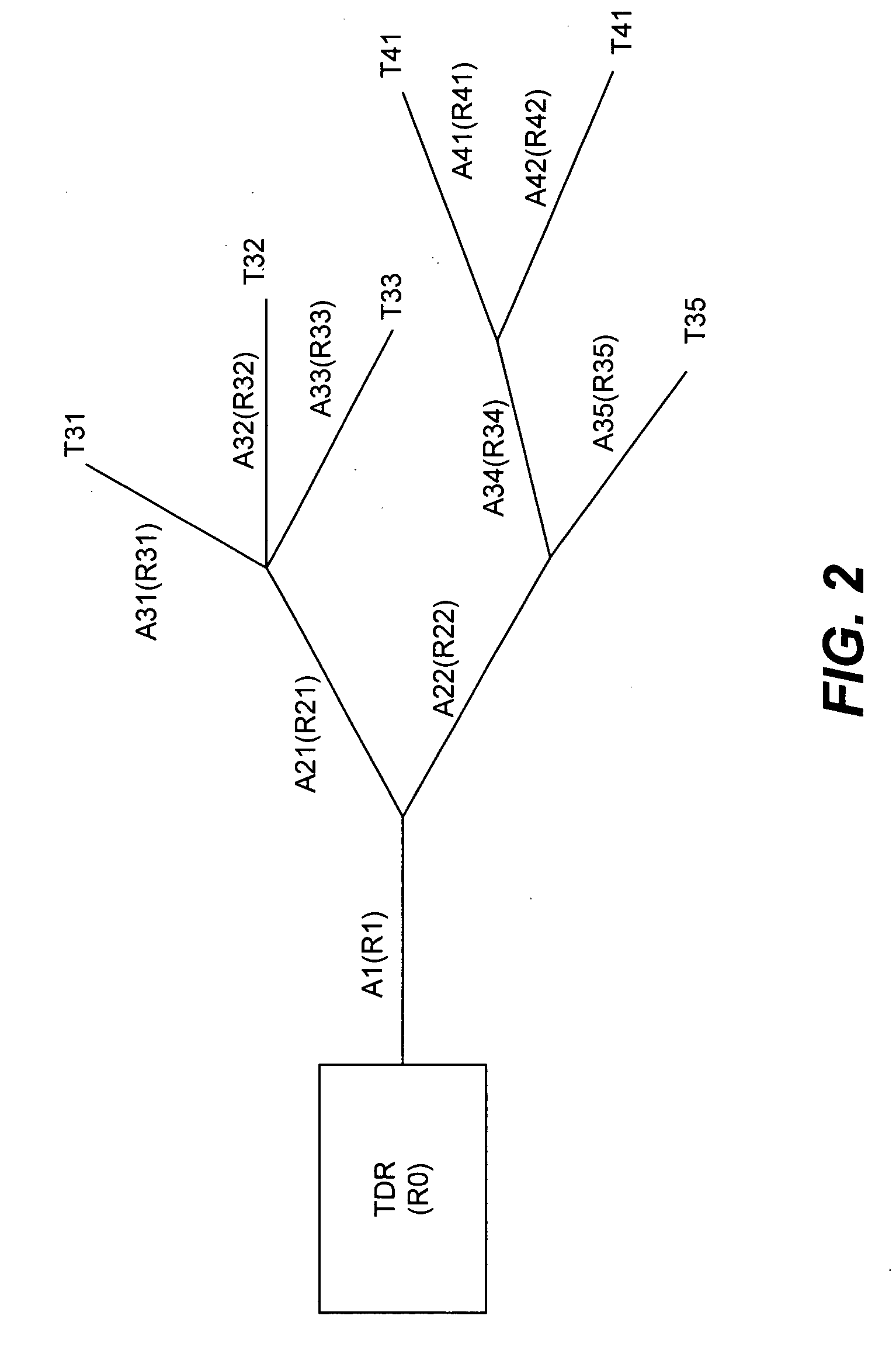
This is because branches in the network add a further level of complexity to the reflectometry response.
Junctions of wires create an impedance mismatch that can be difficult to distinguish from other types of impedance mismatch.
The number of reflections also tends to grow exponentially with the number of branches in the network; hence, complex network topologies produce extremely complex reflectometry responses.
As a result, even if a distance measurement to a fault can be obtained, the result may be ambiguous, since which branch the fault is located on is not provided.
Analyzing networks of unknown topology can therefore be particularly difficult.

Method used


Image

  • Wire network mapping method and apparatus using impulse responses
  • Wire network mapping method and apparatus using impulse responses
  • Wire network mapping method and apparatus using impulse responses

Examples


Embodiment Construction

[0024] Reference will now be made to the exemplary embodiments illustrated in the drawings, and specific language will be used herein to describe the same. It will nevertheless be understood that no limitation of the scope of the invention is thereby intended. Alterations and further modifications of the inventive features illustrated herein, and additional applications of the principles of the inventions as illustrated herein, which would occur to one skilled in the relevant art and having possession of this disclosure, are to be considered within the scope of the invention.

[0025] Throughout this application the term wire network is used to refer in a general sense to a network of signal conductors. Although signal conductors are most typically wires—including for example bare or insulated wires, twisted pairs, and coaxial cables—signal conductors may be in the form of printed circuit board traces, waveguides, piece of rebar in a concrete structure, or even wireless channels. Henc...


PUM


Abstract

A method and apparatus for mapping a wire network is disclosed. The method includes obtaining a reflectometry test signal of the wire network. An estimated network impulse response is estimated from the reflectometry response. A wire network model is then initialized, and iteratively improved by simulating an impulse response of the wire network model and adjusting the wire network model to reduce differences between the simulated impulse response and estimated network impulse response.

Description

[0001] This application claims the benefit of U.S. Application No. 60 / 648,836 filed on Jan. 31, 2005, entitled “Wire Network Mapping Method and Apparatus Using Impulse Reponses,” which is herein incorporated by reference.BACKGROUND OF THE INVENTION [0002] 1. Field of the Invention [0003] The present invention relates generally to the field of electronic testing. More particularly, the present invention relates to devices and methods for mapping signal paths in electronic systems [0004] 2. Related Art [0005] Electronic systems are ubiquitous. An essential component of these systems is their internal signal paths, most typically provided by wired interconnects. Failures in the wiring frequently result in failure of the system. For example, aging wiring in buildings, aircraft and transportation systems, consumer products, industrial machinery, etc. is among the most significant potential causes of catastrophic failure and maintenance cost in these structures. High profile airline crash...

Claims


Application Information

Patent Timeline
Patent Type & Authority Applications(United States)
IPC IPC(8): H04M9/08
CPCG01R31/11
Inventor LO, CHETFURSE, CYNTHIA
Owner UNIV OF UTAH RES FOUND
Learn More