Rotary compressor

Inactive Publication Date: 2006-08-17
SANYO ELECTRIC CO LTD
View PDF4 Cites 7 Cited by
  • Summary
  • Abstract
  • Description
  • Claims
  • Application Information

AI Technical Summary

Benefits of technology

[0011] According to the rotary compressor of the first aspect of the present invention, the thickness of the first roller is set to be larger than that of the second roller. Therefore, for example, as in the second aspect of the present invention, the heights of the opposite cylinders are set to be equal, the diameters of the opposite eccentric portions are set to be equal, and the inner diameter of the first cylinder is set to be larger than that of the second cylinder. Accordingly, it is possible to increase the thickness of the first roller.
[0012] Moreover, even in a case wh

Problems solved by technology

However, the high inner pressure type rotary compressor has a large pressure difference between the cylinder of the first rotary compression element and the sealed container.
In a case where the thickness of the roller of the first rotary compression element is reduced to reduce a sealing width by th

Method used


Image

  • Rotary compressor
  • Rotary compressor
  • Rotary compressor

Examples


Example

Embodiment 1

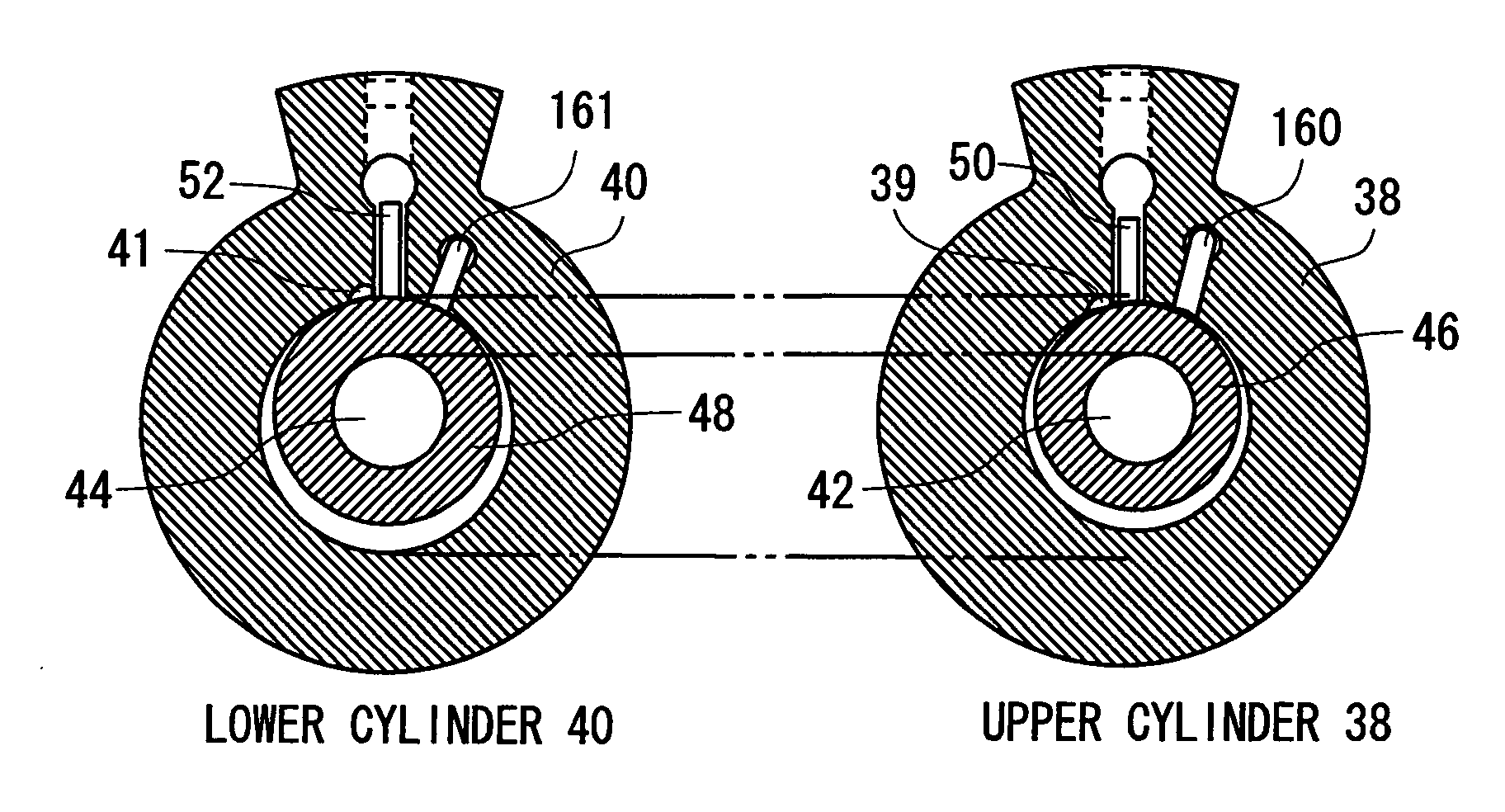
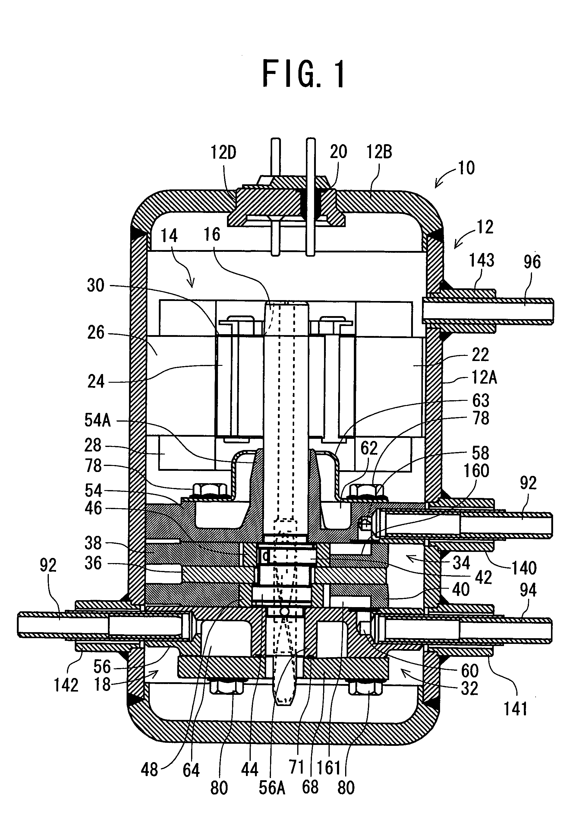
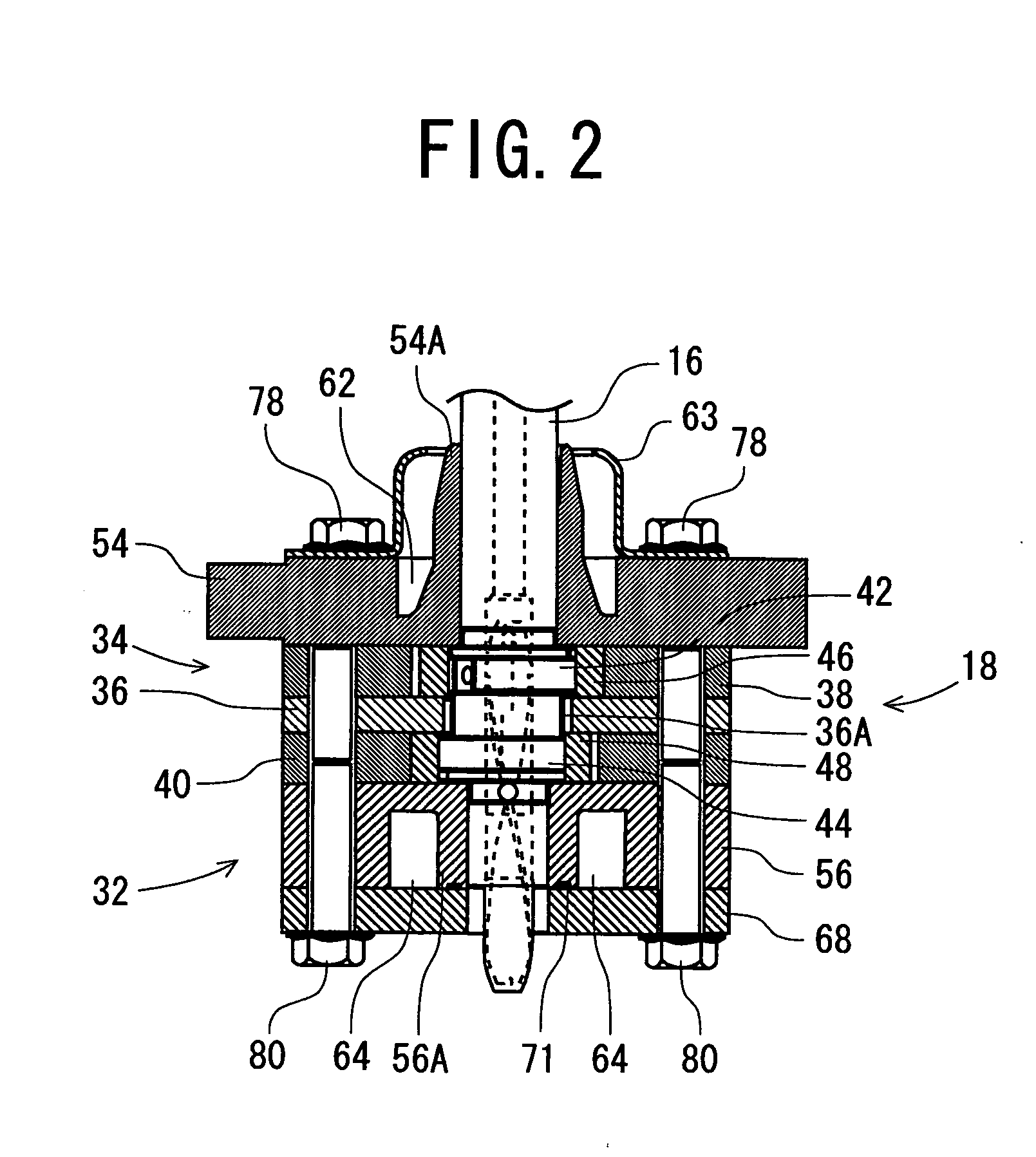
[0021]FIG. 1 is a vertical sectional side view showing a so-called high inner pressure type multistage compression system rotary compressor 10 as one embodiment of the rotary compressor of the present invention. In the compressor, a refrigerant compressed by a first rotary compression element 32 is compressed by a second rotary compression element 34, and sent into a sealed container 12. FIG. 2 shows a vertical sectional side view of the first and second rotary compression elements 32, 34 of the rotary compressor 10, and FIG. 3 shows a sectional plan view of upper and lower cylinders 38, 40 of the first and second rotary compression elements 32, 34, respectively. It is to be noted that FIGS. 1 and 2 show different sections, respectively.

[0022] In the rotary compressor 10 of each drawing, in the vertical cylindrical sealed container 12 constituted of a steel plate, there are disposed an electromotive element 14 as a driving element, and a rotary compression mechanism se...

Example

Embodiment 2

[0056] Next, another embodiment of a rotary compressor of the present invention will be described with reference to FIGS. 4 and 5. FIG. 4 shows a vertical sectional side view showing first and second rotary compression elements 32, 34 of the rotary compressor in the present embodiment, and FIG. 5 shows a sectional plan view of cylinders 138, 140, respectively. It is to be noted that in FIGS. 4 and 5, components denoted with the same reference numerals as those of FIGS. 1 to 3 produce identical or similar effects.

[0057] In the rotary compressor of the present embodiment, in a vertical cylindrical sealed container constituted of a steel plate, there are disposed an electromotive element as a driving element, and a rotary compression mechanism section 18 constituted of the first rotary compression element 32 driven by a rotation shaft 16 of this electromotive element 14 and the second rotary compression element 34 whose displacement volume is smaller than that of the firs...


PUM


Abstract

In a high inner pressure type multistage compression system rotary compressor whose object is to improve sealability of a first rotary compression element and which includes a second rotary compression element having a displacement volume being smaller than that of the first rotary compression element and in which a refrigerant compressed by the first rotary compression element is compressed by the second rotary compression element to discharge the refrigerant into a sealed container, heights of a first cylinder of the first rotary compression element and a second cylinder of the second rotary compression element are set to be equal, diameters of both of eccentric portions are set to be equal, an inner diameter of the first cylinder is set to be larger than that of the second cylinder, and a thickness of a first roller is set to be larger than that of a second roller.

Description

BACKGROUND OF THE INVENTION [0001] The present invention relates to a rotary compressor which is provided with a driving element and first and second rotary compression elements driven by a rotation shaft of this driving element, the elements being disposed in a sealed container, and in which a refrigerant compressed by the first rotary compression element is compressed by the second rotary compression element to send the refrigerant into the sealed container. [0002] Heretofore, in this type of rotary compressor, for example, a high inner pressure type rotary compressor, a rotation shaft is of a vertically disposed type. The compressor includes: a driving element; a first rotary compression element driven by the rotation shaft of this driving element; and a second rotary compression element whose displacement volume is smaller than that of the first rotary compression element, the elements being disposed in a sealed container. The first and second rotary compression elements are con...

Claims


Application Information

Patent Timeline
IPC IPC(8): F01C19/00F04C27/00F04C15/00
CPCF01C21/08F04C18/3564F04C23/001F04C23/008E04C3/36E04H12/02
Inventor SATO, KAZUYA
Owner SANYO ELECTRIC CO LTD
Why Eureka
Try Eureka