Sealed combustion gas-fired infrared heater

a gas-fired infrared heater and sealing technology, which is applied in the direction of gaseous heating fuel, combustion types, stoves or ranges, etc., can solve the problems of snuffing of flames, carbon monoxide formation, and combustion products that are not admixed

Inactive Publication Date: 2006-08-17
EICHENLAUB JOHN E
View PDF24 Cites 7 Cited by
  • Summary
  • Abstract
  • Description
  • Claims
  • Application Information

AI Technical Summary

Problems solved by technology

However, one problem with this approach is that turbulence in the flame area creates enough admixture of combustion products with incoming combustion air to interfere with clean combustion (e.g., thes

Method used


Image

  • Sealed combustion gas-fired infrared heater
  • Sealed combustion gas-fired infrared heater
  • Sealed combustion gas-fired infrared heater

Examples


Embodiment Construction

[0017] Embodiments of the present invention will be described hereinafter with reference to the accompanying drawings.

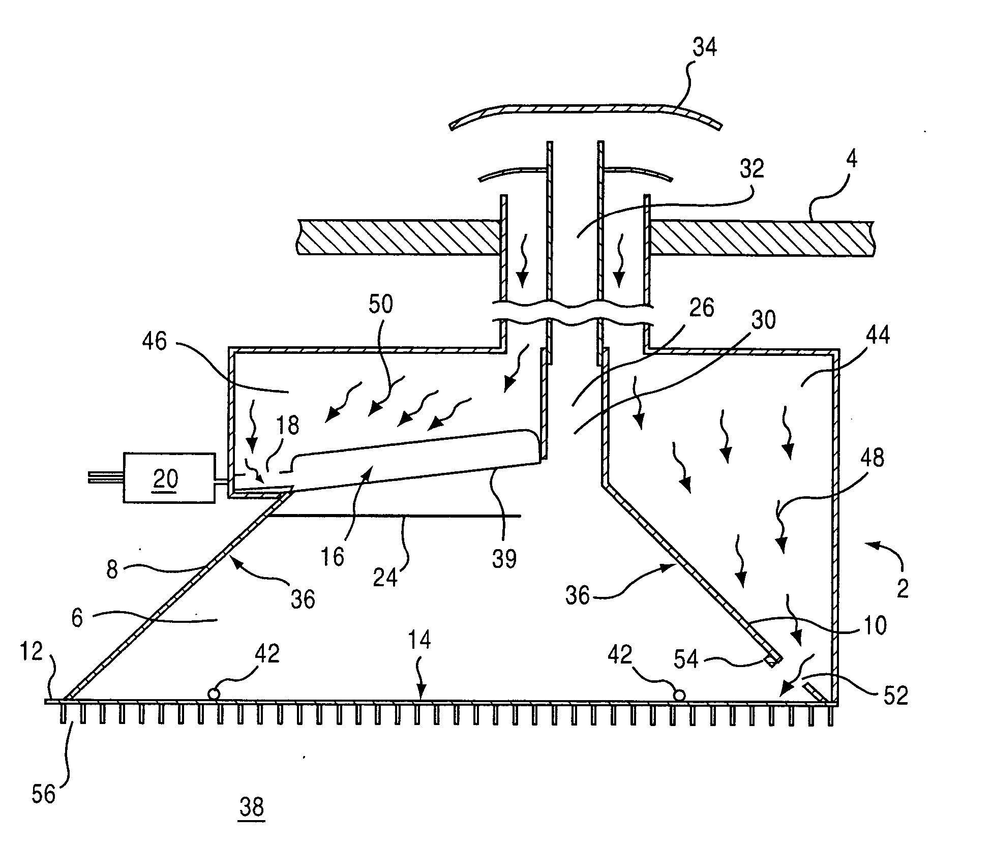
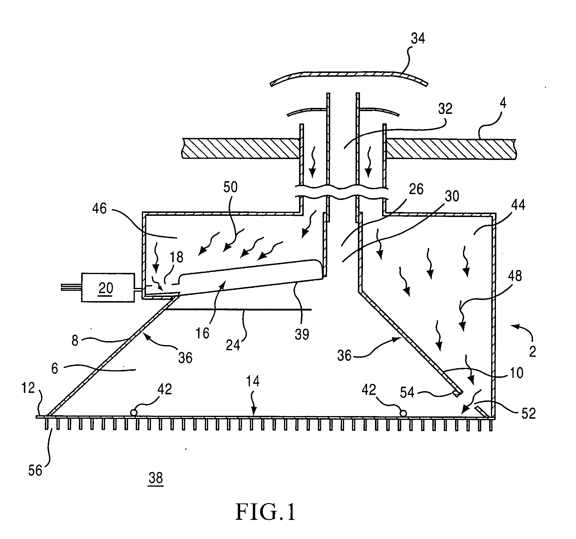
[0018] Referring to FIG. 1, the heater of the invention is designated by a reference numeral 2, and as shown in an exemplary position as being secured to a ceiling 4 of an enclosure to be heated (e.g., tent, bathroom, ice-fishing shanty, mobile home, etc.) A combustion chamber 6 is provided with generally upright side walls 8, 10, a front and rear wall (not shown) and a bottom wall 12, with a radiation-transmissive port therein. The port may extend between the side walls 8, 10 and the front and rear walls of the combustion chamber 6, although it may be desirable, in some instances, to have a smaller port. A sealing barrier 14 is located to close the port, and may be fastened by clamps, spline in groove, or the like (not shown) to the periphery of the front, rear, and side walls of the combustion chamber 6.

[0019] The sealing barrier 14 is desirably of a thin, flexib...


PUM


Abstract

A gas fired infrared heater is provided that includes a burner, a combustion chamber, a cooling air passage for supplying cooling air to the combustion chamber, a combustion air passage for supplying combustion air to the burner; and an outlet passage allowing combustion product gases to exit the combustion chamber. The cooling air passage is separate from the combustion air passage. The cooling air passage and the combustion air passage both draw from the same pressure zone into which combustion products exit.

Description

FIELD OF THE INVENTION [0001] The present invention relates to a gas-fired infrared heating apparatus; particularly a heating apparatus that completely segregates an incoming combustion air flow from an incoming radiation-transmissive panel cooling air flow, both of which draw from the pressure zone to which combustion products exit, and that segregates both from the combustion chamber itself. BACKGROUND OF THE INVENTION [0002] A heating device having a fuel-fired radiant burner has long been used for heating various enclosures. The heating device here described includes a thin, radiation-transmissive panel that transmits infrared radiation into the space to be heated (e.g., room, tent) and also seals a combustion chamber which houses a radiant from the space being heated. To maintain the integrity of the heating device, the panel must be cooled. [0003] One way to cool the panel is to have a stream of cooling air flow (e.g., by convection) over the panel. An additional way to cool t...

Claims


Application Information

Patent Timeline
IPC IPC(8): F23D3/40
CPCF23D14/14F23D2214/00F23J2211/101F24C3/004F23D14/151F23D14/145
Inventor EICHENLAUB, JOHN E.
Owner EICHENLAUB JOHN E
Why Eureka
Try Eureka