Battery connection plate

a battery electrode and connection plate technology, applied in the direction of cell components, cell component details, coupling device connections, etc., can solve the problems of incomplete connection of the battery electrode, disposed of, and incomplete connection of the plate body to the battery electrode, so as to prevent the connection of the voltage detection terminal and facilitate assembly.

Active Publication Date: 2006-08-17
YAZAKI CORP +1
View PDF4 Cites 15 Cited by
  • Summary
  • Abstract
  • Description
  • Claims
  • Application Information

AI Technical Summary

Benefits of technology

[0030] In the invention, the guide wall for guiding the interconnecting portion is formed on the plate body, and therefore the voltage detection terminal is prevented from being displaced out of position, and besides when fastening the battery cell to the battery connection plate by the bolt-nut connection, the bus bar connecting portion is prevented from rotating with the nut. Therefore, the battery connection plate can be easily assembled without damaging the bus bar connecting portion.

Problems solved by technology

However, it has the following problems.
Namely, there is a slight variation in the length of the individual battery cells, and as a result there has been a fear that the plate-like bus bar connecting portion, disposed in abutting relation to the plate body, is incompletely connected to the battery electrode.
On the other hand, in this kind of battery connection plate, a complicated wiring pattern is required to be formed by bus bars z6 within a limited space, and therefore even the above structure involves problems.
And besides, in battery connection plates today, the layout of bus bars and voltage detection terminals has been extremely complicated, and there has been a fear that the bus bar and the voltage detection terminal interfere with each other.

Method used


Image

  • Battery connection plate
  • Battery connection plate
  • Battery connection plate

Examples


Embodiment Construction

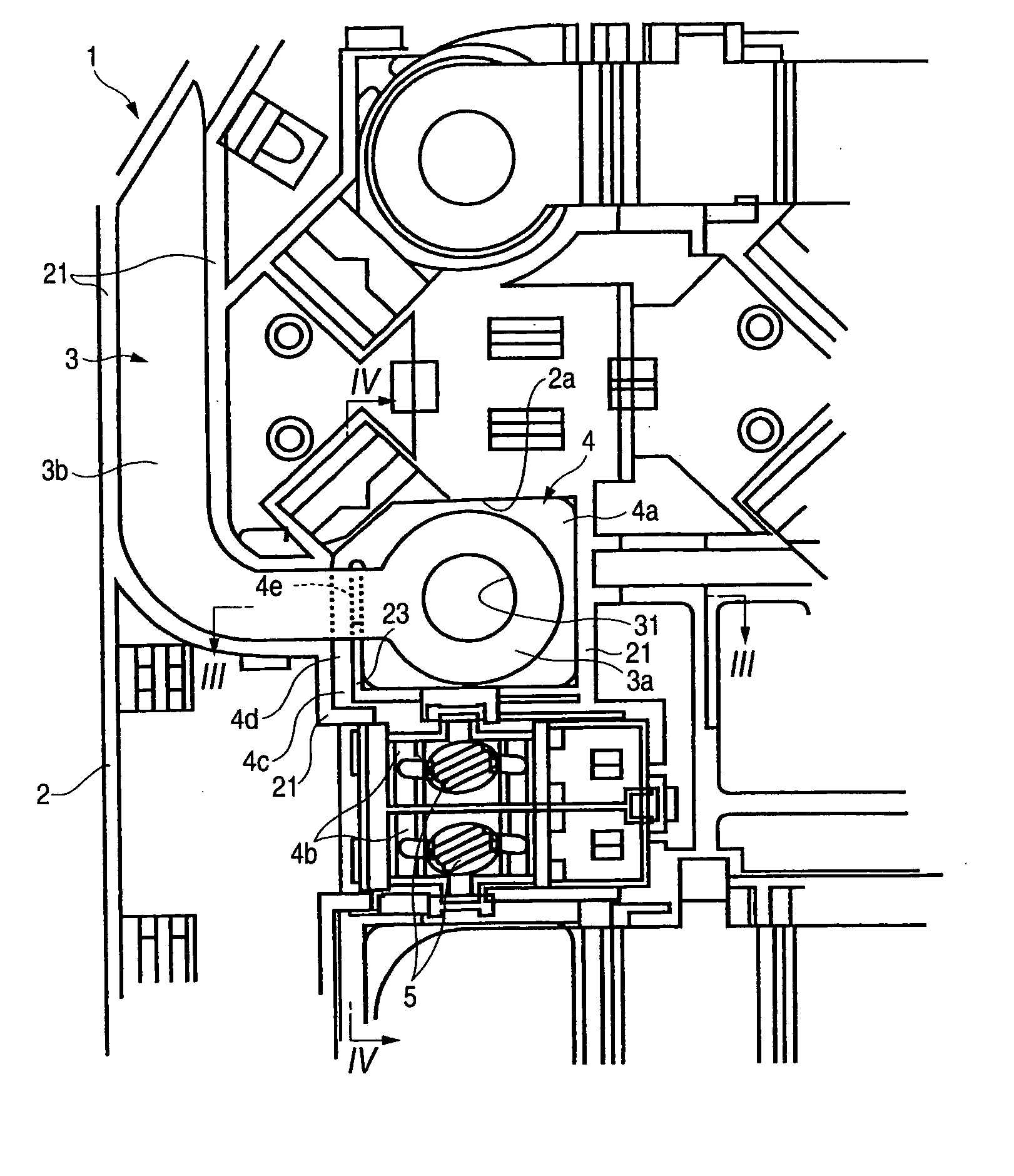
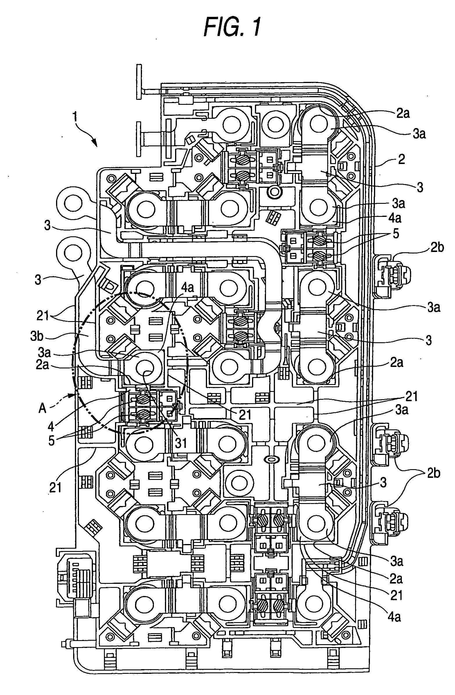
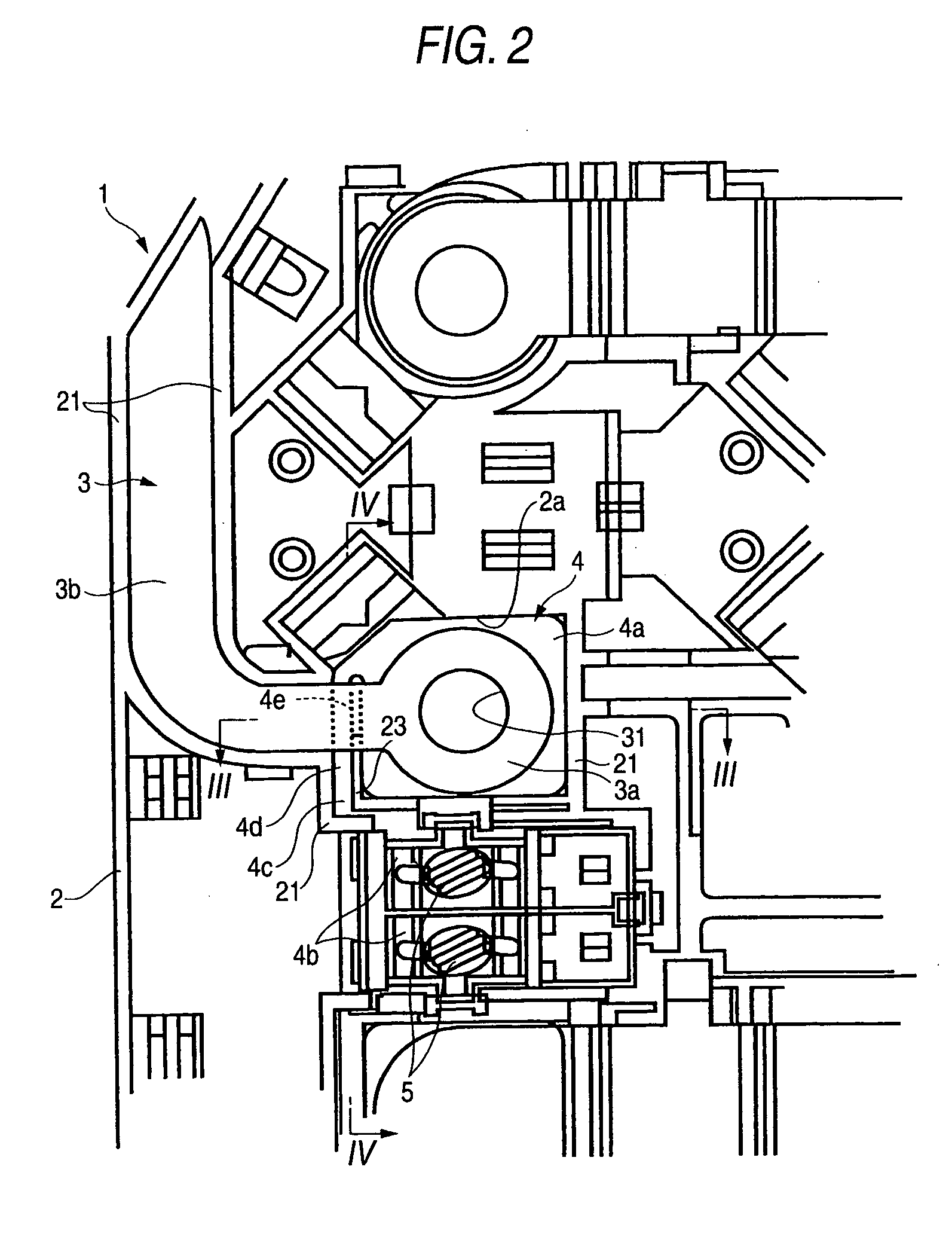
[0039] A preferred embodiment of a battery connection plate of the present invention will now be described. In the illustrated battery connection plate of this embodiment, a plurality of battery cells of a generally bar-shape, having battery electrodes each with external threads, are arranged parallel in an upstanding condition within a cell containing case or the like, and are collectively electrically connected together by this battery connection plate. For convenience', first, the battery connection plate will be described, and then important portions of the invention will be described.

[0040] In the drawings, reference numeral 1 denotes the battery connection plate, reference numeral 2 denotes a plate body, reference numeral 3 denote bus bars, and reference numeral 4 denotes voltage detection terminals.

[0041] The battery connection plate 1 of this embodiment comprises the plate body 2, the bus bars 3, and the voltage detection terminals 4.

[0042] As shown in FIG. 1, the plate b...


PUM

PropertyMeasurementUnit
voltageaaaaaaaaaa
lengthaaaaaaaaaa
resilient deformationaaaaaaaaaa

Abstract

A voltage detection terminal includes a bus bar connecting portion which is connected to a battery electrode and a bus bar by bolt-nut connection, a detector connecting portion connected to voltage detector, and an interconnecting portion interconnecting the bus bar connecting portion and the detector connecting portion. A gap for absorbing a length variation of a battery cell is formed between a plate body and the bus bar connecting portion, and a slanting portion for preventing the interconnecting portion from interference with the bus bar is formed at part of the interconnecting portion.

Description

BACKGROUND OF THE INVENTION [0001] 1. Field of the Invention [0002] This invention relates to a battery connection plate for connection to battery cells used, for example, in an electric car, a hybrid car or the like. [0003] 2. Related Art [0004] In an electric car using an electric motor, a hybrid car using both of an electric car and an internal combustion engine, or the like, generally, a plurality of battery cells of a generally bar-shape, having battery electrodes each with external threads, are arranged parallel in an upstanding condition, and are collectively electrically connected together by this battery connection plate. [0005] This conventional battery connection plate is adapted to be connected to the battery electrodes as described above, and this battery connection plate comprises bus bars having battery electrode connecting portions having through holes for respectively passing the battery electrodes, formed on and projecting respectively from distal ends of the plura...

Claims


Application Information

Patent Timeline
Patent Type & Authority Applications(United States)
IPC IPC(8): H01R3/00H01M50/528
CPCH01R11/26H01R11/281H01R13/665H01R27/00
Inventor SAITO, KAZUAKIIKEDA, TOMOHIROSHIBUYA, KENTAROKOSAKA, HIROSHISATO, SEIICHI
Owner YAZAKI CORP
Why Eureka
Try Eureka