Fitting for liquids

a technology for armatures and liquids, applied in the direction of fluid pressure control, process and machine control, instruments, etc., can solve the problems of insufficient regard, troublesome removal of hoses after filling or re-filling process, and inability to check

Inactive Publication Date: 2006-08-24
HANS SASSERATH GMBH & CO KG
View PDF8 Cites 8 Cited by
  • Summary
  • Abstract
  • Description
  • Claims
  • Application Information

AI Technical Summary

Benefits of technology

[0043] Preferably means are provided at said connection for the expansion tank for generating a flow in an expansion tank connected thereto. Thereby stagnant water in the expansion tank is avoided.

Problems solved by technology

For continuous operation, however, this is also not regarded as sufficient.
As the removal of the hose after the filling or re-filling process is troublesome and, in addition, cannot be checked, fixed installations of pipe disconnectors are known (for example EP 0,972,995 A1).
This is time-consuming.
This is time- and money-consuming.

Method used


Image

  • Fitting for liquids
  • Fitting for liquids
  • Fitting for liquids

Examples


embodiment 2

ector with Downstream Pressure Reducer

[0082] In FIG. 3 numeral 110 denotes an armature housing. The armature housing 110 is elongated and forms a sleeve-shaped jacket part 112. An inlet 114 and an outlet 116 are distantly provided at the armature housing 110. Inlet 114 and outlet 116 are provided at the side of the armature housing 110 and connected to connection necks 118 and 120, respectively. The connection necks 118 and 120 run perpendicular to the longitudinal axis of the jacket part 112 in the drawing plane of the Figure. The connection necks 118 and 120 end in a common connection plane which is perpendicular to the drawing plane of the figure and parallel to the longitudinal axis.

[0083] For connecting the armature housing a connection piece 122 is provided. The connection piece 122 has an inlet neck 124 and an outlet neck 126 aligned thereto. The connection piece 122 is installed into a liquid pipe (not shown) with these inlet- and outlet necks 124 and 126, respectively. Thi...

embodiment 4

Assembly with Pressure Reducer

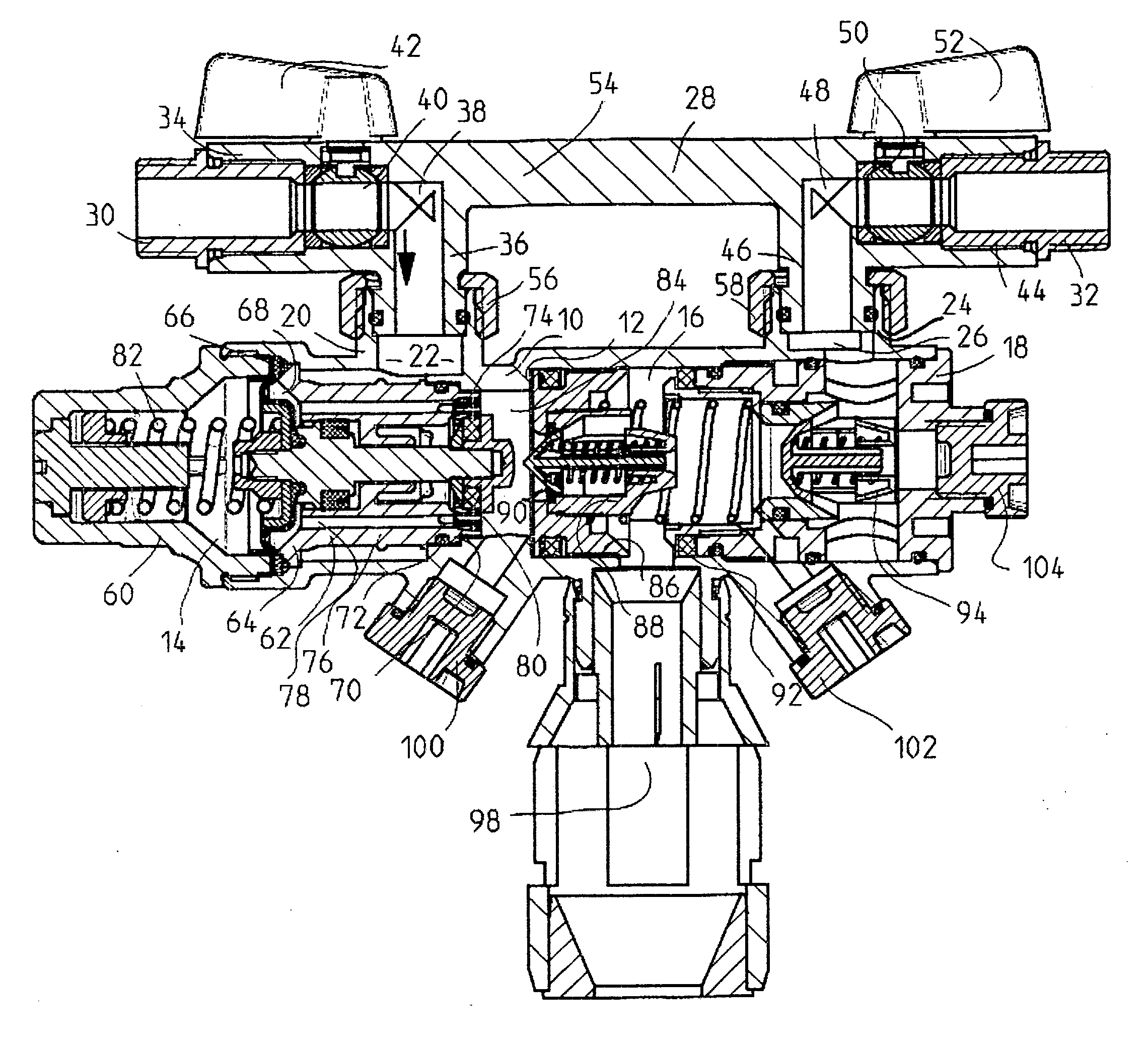
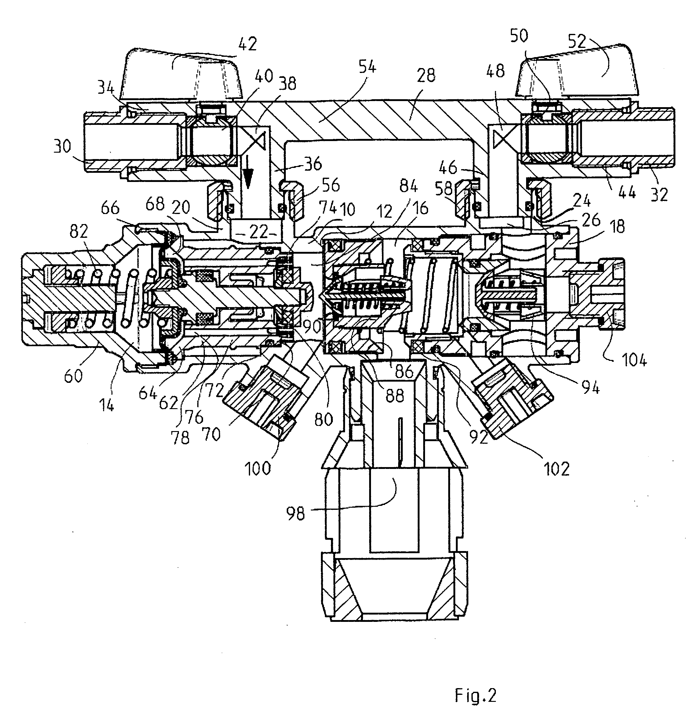
[0109] In FIG. 12 an embodiment is shown being a modification of the safety assembly according to FIGS. 4 to 11. Here a pressure reducer 294 is integrated into the assembly. Apart from that the assembly is not changed with respect to the assembly of FIG. 4. For connecting the pressure reducer 294 a connection neck 296 is provided in the second armature part 214. The pressure reducer 294 is cartridge-like inserted into the armature part 214 through the connection neck 296. Such a cartridge-like pressure reducer is already known and need not be described here in further detail.

[0110] The pressure reducer 294 is arranged in the removable armature part 214 downstream of the backflow preventer 218. In the case of a need of service the pressure reducer can be removed or replaced or serviced just like the backflow preventer 218 as described above. It is a particular advantage that the installation size with the additional pressure reducer does not change comp...

embodiment 5

Assembly with Pressure Reducer and Expansion Tank

[0112] A safety valve assembly with an expansion tank is described with reference to the following figures, which is apart from that identical to the safety valve assembly of embodiment 4.

[0113] In FIG. 13 a complete safety valve assembly is shown. The safety valve assembly is provided with an expansion tank 298 with a common design at the neck 220 The expansion tank 298 is only partly indicated. A pressure reducer 294 is arranged upstream of the expansion tank 298. The inlet pressure of the installation is kept at a constant value by the pressure reducer 294. The expansion tank then has its maximum receiving volume. In installations where there is a pressure reducer present at a different position anyway or where the pressure is not very high, this pressure reducer is not needed. The connection is then closed with a plug.

[0114] For avoiding stagnant water in the expansion tank it is advantageous to generate a flow. For this purpose...


PUM


Abstract

A fitting assembly for liquids adapted to be installed in a pipeline includes an inlet and first shut-off governing said inlet, an outlet and second shut-off governing said outlet, and components which require occasional or regular servicing arranged in a flow path between said first and second shut-offs. The said fitting assembly comprises a first fitting part adapted to be fixedly installed in said pipeline by means of said first and second shut-offs, said first fitting part having first and second connections between said first and second shut-offs, said fitting assembly comprises a second fitting part, said second fitting part containing the components which require occasional or regular servicing, and a means for removably attaching said second fitting part to said connecting means of said first fitting part.

Description

BACKGROUND OF THE INVENTION [0001] 1. Field [0002] The invention relates to an armature for liquids for the installation in a pipe for liquids comprising an inlet passage for liquids which is adapted to be shut off by first shut-off means and an outlet passage for liquids which is adapted to be shut off by second shut-off means and one or more components in need of servicing which are positioned between said first and second shut-off means. [0003] Such components in need of servicing may be, in particular, filters, backflow preventers, pipe disconnectors, pressure reducers and any other valves as they may be used in water armatures in various embodiments and arrangements for various purposes. [0004] Examples for such a water armature are pipe disconnector armatures or safety assemblies for protecting drinking water heaters. [0005] 2. State of the Art [0006] A safety assembly for protecting drinking water heaters normally comprises a housing, an inlet and an outlet, a flow passage be...

Claims


Application Information

Patent Timeline
Patent Type & Authority Applications(United States)
IPC IPC(8): F17D1/08
CPCF24H9/126Y10T137/87917F24H9/136
Inventor HECKING, WILLI
Owner HANS SASSERATH GMBH & CO KG
Why Eureka
Try Eureka