Assembly and method for determining thermal properties of a formation and forming a liner

a technology of thermal properties and liner, which is applied in the field of in situ determination of thermal properties, can solve the problems of inaccurate with respect to particular samples, laboratory analysis will not provide complete data for all zones, and the method of laboratory analysis cannot enable real-time data acquisition

Inactive Publication Date: 2006-08-24
HALLIBURTON ENERGY SERVICES INC
View PDF26 Cites 92 Cited by
  • Summary
  • Abstract
  • Description
  • Claims
  • Application Information

AI Technical Summary

Problems solved by technology

The laboratory method does not enable real-time data acquisition, and can only be accurate with respect to the particular sample acquired.
Since formation properties typically change with depth, it is likely that the laboratory analysis will not provide complete data for all zones of the formation.
This method has some limitations, including the inability to make accurate measurements through casing to determine formation properties behind the casing and the cement that surrounds it.
Although this approach is technically sufficient, and valuable formation characteristics can be determined using this methodology, this approach has largely been ignored in practice.
One possible explanation is that operators are not willing to incur additional capital and operating costs for a heat source that is provided solely for thermal property measurements.
Thus, most commercial downhole systems do not include heat sources that enable in situ measurements of thermal properties.
Further, although the '128 Patent and the '227 Patent mention the concept of a heat drilling tip that may also be used as a heat source for enabling in situ determinations of thermal properties, such heat drilling tips have proven to be too slow for commercial success.
However, because rock is very slow to spall or melt utilizing such techniques, the heat drilling tip progresses at only 3-6 feet per hour.
Therefore, the heat tip has not achieved commercial recognition or success as a viable drilling alternative.

Method used


Image

  • Assembly and method for determining thermal properties of a formation and forming a liner
  • Assembly and method for determining thermal properties of a formation and forming a liner
  • Assembly and method for determining thermal properties of a formation and forming a liner

Examples


Embodiment Construction

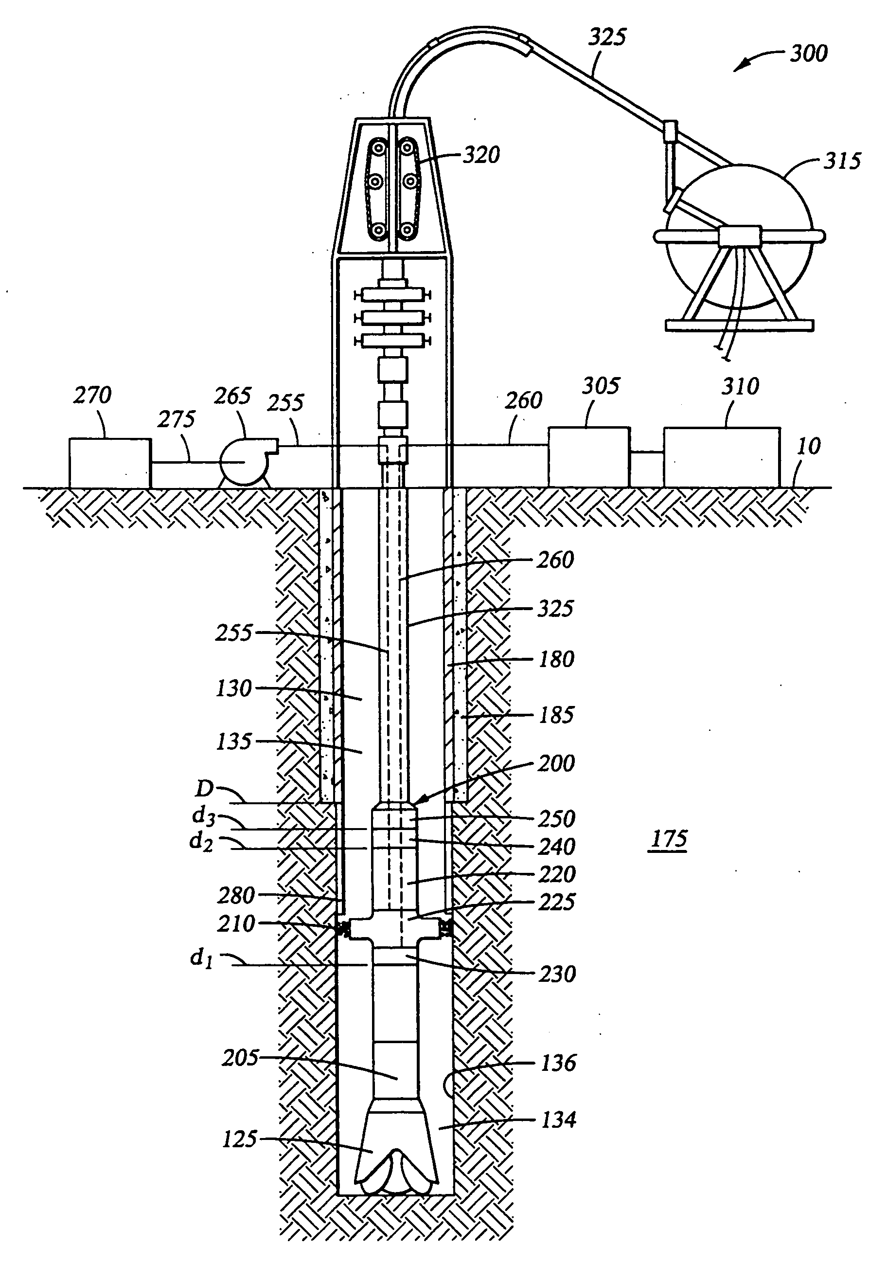
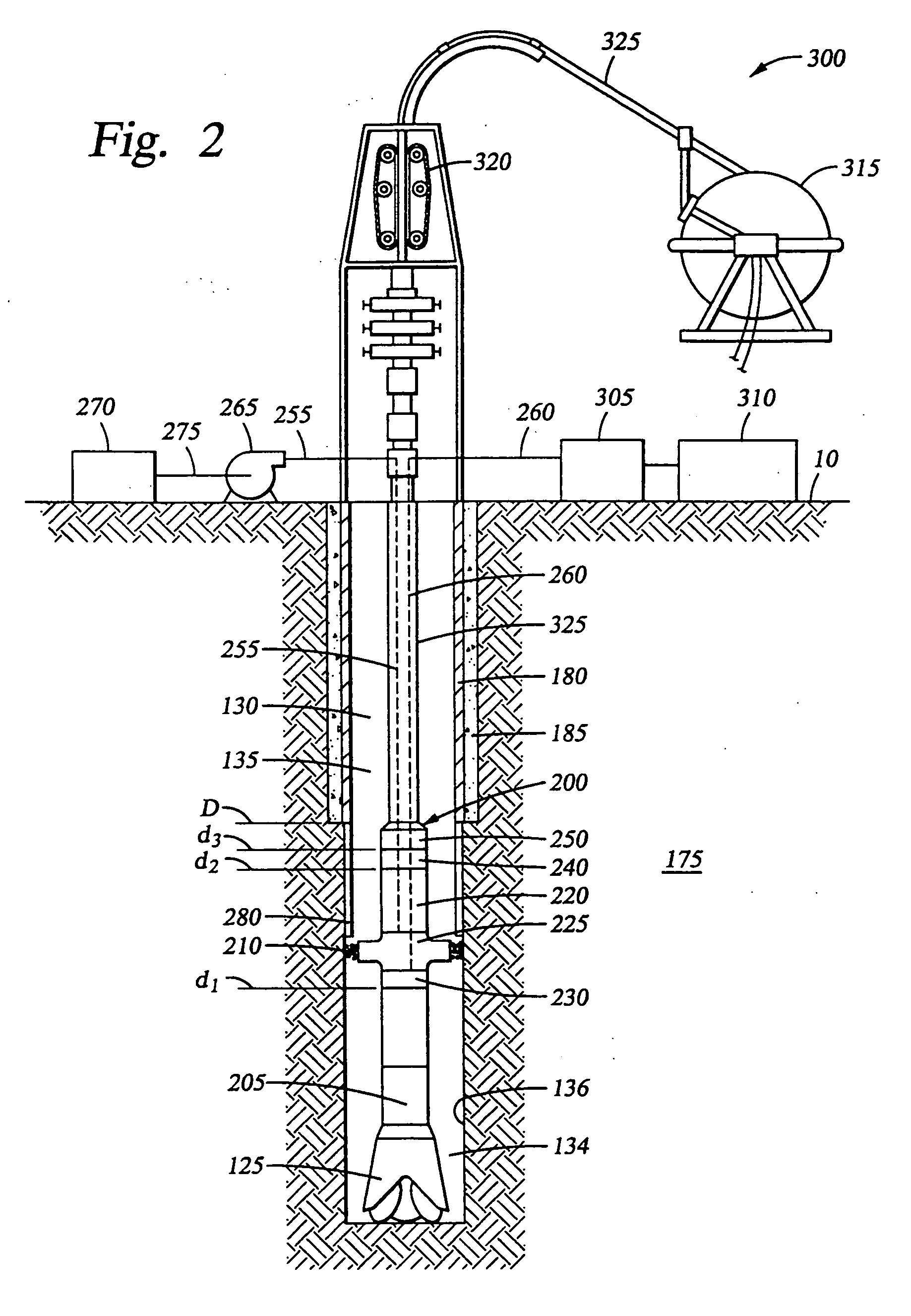
[0036] Laser technology has flourished in recent years, largely through the expansion of atomic physics, the invention of fiber optics, and advances in military defense capabilities. Through these efforts, tremendous advances have occurred, for example, in laser power generation, efficiency and transmission capabilities. Improvements in lasers and other thermal technologies have made it possible to perform wellbore operations, such as wellbore stabilization, drilling, and perforating, utilizing new techniques. Because thermal technologies offer significant advantages over conventional methods, they are gaining rapid acceptance in the petroleum industry.

[0037] Lasers and other thermal technologies provide a heat source downhole to perform a primary function, such as wellbore stabilization, drilling, or perforating through casing. The heat source may also be utilized for the secondary but important purpose of determining thermal properties of the formation. Accordingly, measurements ...


PUM

PropertyMeasurementUnit
lengthaaaaaaaaaa
lengthaaaaaaaaaa
thermal propertiesaaaaaaaaaa

Abstract

A method comprises heating a formation adjacent a selected depth level within a wellbore extending into the formation, forming a temporary liner in the wellbore, measuring a first temperature of the formation at the selected depth level at a first time after heating the formation, measuring a second temperature of the formation at the selected depth level at a second time after heating the formation, and combining the temperature measurements to derive an indication of thermal properties of the formation. An apparatus comprises a coiled tubing drillstring extending into a wellbore, an assembly supported by the drillstring, the assembly comprising an extruder that extrudes a liner material onto a wall of the wellbore, a heat source that heats the liner material and a formation, and at least one temperature sensor that measures a temperature of the formation.

Description

CROSS-REFERENCE TO RELATED APPLICATIONS [0001] The present application is a divisional claiming priority to pending U.S. patent application Ser. No. 10 / 457,645, filed Jun. 9, 2003 and entitled “Determination of Thermal Properties of a Formation,” which is hereby incorporated by reference herein in its entirety. [0002] The present application is also related to a continuation application, U.S. patent application Ser. No. ______, filed concurrently herewith on ______ and entitled “Assembly for Determining Thermal Properties of a Formation While Drilling or Perforating,” which is hereby incorporated by reference herein in its entirety.STATEMENT REGARDING FEDERALLY SPONSORED RESEARCH OR DEVELOPMENT [0003] Not applicable. BACKGROUND [0004] 1. Field of the Invention [0005] The present invention relates to the evaluation of downhole formations from the in situ determination of thermal properties. More particularly, the present invention relates to the in situ determination of thermal prope...

Claims


Application Information

Patent Timeline
Patent Type & Authority Applications(United States)
IPC IPC(8): E21B36/00E21B7/14E21B33/138E21B43/10E21B43/11E21B47/06G01N25/00G01N25/18G01V9/00
CPCE21B7/14E21B33/138E21B43/10E21B43/11E21B47/065G01N25/005G01N25/18G01V9/00E21B47/07
Inventor SMITH, HARRY D. JR.
Owner HALLIBURTON ENERGY SERVICES INC
Why Eureka
Try Eureka