Block orientation cylinder

Inactive Publication Date: 2006-08-24
STIBBARD JAMES SPENSER
View PDF14 Cites 2 Cited by
  • Summary
  • Abstract
  • Description
  • Claims
  • Application Information

AI Technical Summary

Benefits of technology

[0003] Embodiments of the invention described herein address the need for block orientation and are reasonably quiet

Problems solved by technology

However, vibrating conveyors are usually very noisy and may transmit vibrations through its supporting structure int

Method used


Image

  • Block orientation cylinder
  • Block orientation cylinder
  • Block orientation cylinder

Examples


Embodiment Construction

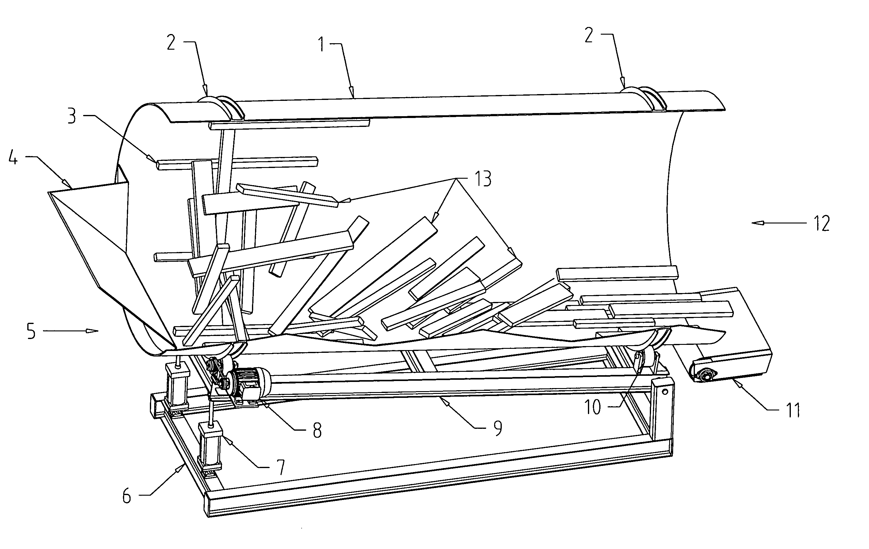
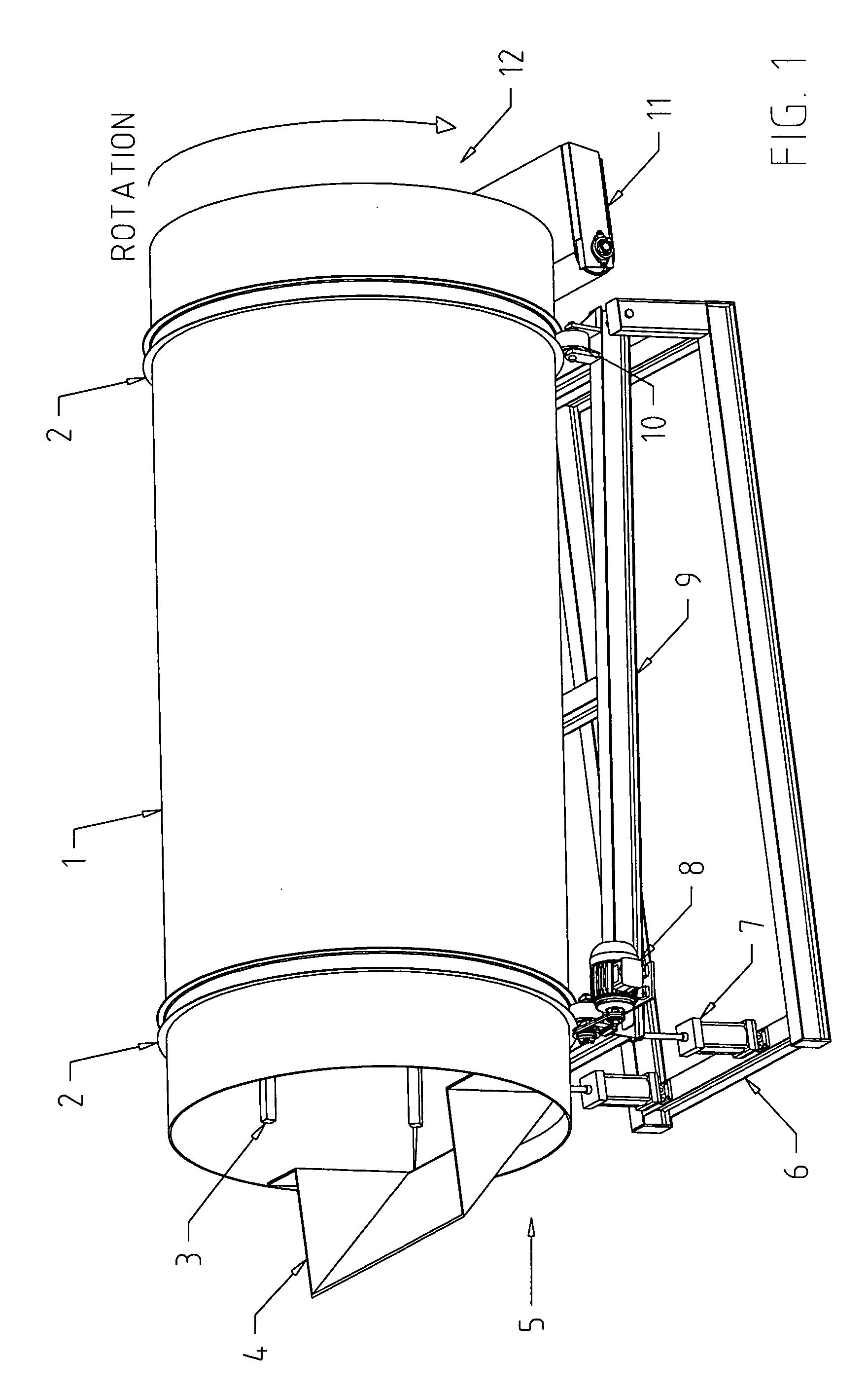
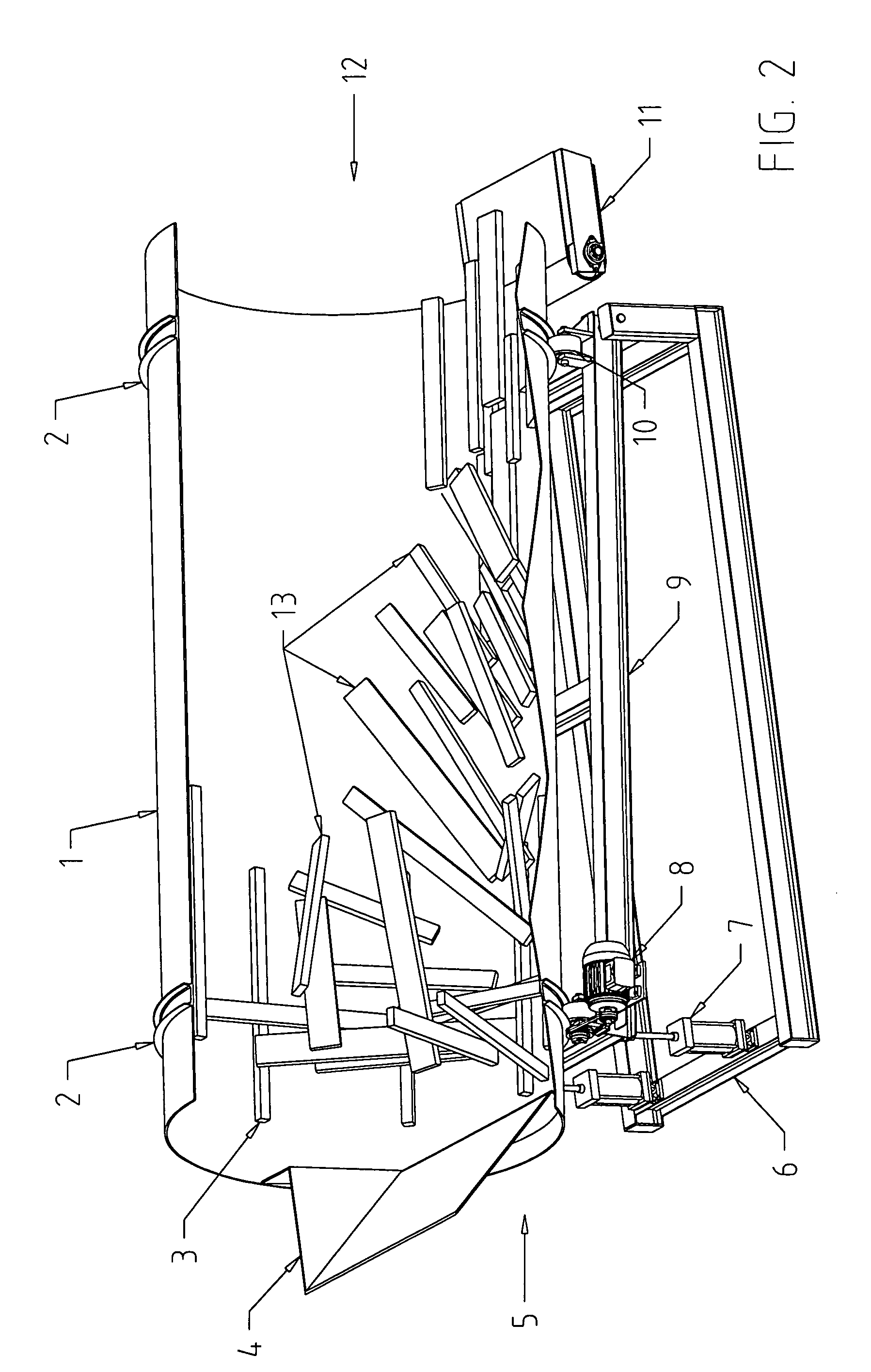
[0010] With reference to FIGS. 1 and 2, an exemplary embodiment of the invention comprises a cylinder (1) with an infeed end (5) and an outfeed end (12). The cylinder (1) is supported at a slight incline to the horizontal plane by a plurality of wheels or rollers (10) attached to a frame (9). In one particular embodiment, the diameter of the cylinder (1) is approximately twelve inches greater than the length of the longest block (13) that is expected to be fed into the cylinder (1). Moreover, in this particular embodiment, the length of the cylinder (1) is approximately four times greater than the length of the longest block (13) to be fed into the cylinder (1). Of course, other embodiments of the invention may be sized as needed for the particular application in which it is employed.

[0011] The rollers (10) are rotatably attached to the frame (9), which is supported by a sub-frame (6). A plurality of guides (2) may be mounted on the exterior of the cylinder (1) to position the cyli...


PUM


Abstract

A rotating cylinder is used to orient wood material, such as but not limited to blocks (e.g., finger joint blocks), preparatory to further processing. The rotating cylinder uses gravity and a tumbling action of the blocks to orient the blocks and move them through the cylinder. Unlike known apparatus such as vibrating conveyors, embodiments of the invention are relatively simple, vibration free, not prone to mechanical stress failures, are quiet, and use minimal horsepower to operate. Furthermore, embodiments of invention may advantageously reduce noise-caused fatigue amongst lumber workers, as well as reduce maintenance and power costs. The rotating cylinder may be part of a larger system for orienting wood material, such as blocks, for further lumber processing.

Description

FIELD OF THE INVENTION [0001] The present invention is directed to apparatus that is used to orient the position of materials in a materials processing system. BACKGROUND OF THE INVENTION [0002] In materials processing systems, apparatus is generally needed to orient materials being processed. Vibrating conveyors are generally used in the lumber industry to orient misaligned blocks that have been delivered from miscellaneous sources, such as walking floor bins. However, vibrating conveyors are usually very noisy and may transmit vibrations through its supporting structure into the floor. Vibrating conveyors also require a large inventory of spare parts and significant horsepower to operate. There is a need for improved apparatus for orienting materials, such as blocks, for further processing. SUMMARY OF THE INVENTION [0003] Embodiments of the invention described herein address the need for block orientation and are reasonably quiet. In addition, embodiments of the invention generall...

Claims


Application Information

Patent Timeline
IPC IPC(8): B65G47/24
CPCB65G47/24
Inventor STIBBARD, JAMES SPENSER
Owner STIBBARD JAMES SPENSER
Why Eureka
Try Eureka