Hydrolysis system to produce hydrogen-oxygen gas as a fuel additive for internal combustion engines

a hydrogen-oxygen gas and internal combustion engine technology, applied in the direction of non-fuel substance addition to fuel, machines/engines, mechanical equipment, etc., can solve the problems of reaching the limit of present design capabilities without yielding a consumer-acceptable product, generating toxic emissions such as carbon monoxide, nitrous oxide, sulfur dioxide, etc., to improve combustion efficiency, reduce internal combustion toxic emissions, and simple operation

Inactive Publication Date: 2011-09-15
NOWICKI RICHARD +3
View PDF12 Cites 32 Cited by
  • Summary
  • Abstract
  • Description
  • Claims
  • Application Information

AI Technical Summary

Benefits of technology

[0021]It is the object of the present invention to provide an electrolysis system for an internal combustion engine which overcomes the problems associated with the current devices used to generate hydrogen and oxygen gases as a fuel additive for internal combustion engines.
[0022]Specifically, it is the object of the present invention to produce sufficient hydrogen gas and oxygen gas to improve the combustion efficiency and reduce toxic emissions of the internal combustion engine to which it is connected. The present invention delivers the generated gases effectively and consistently through the fuel line to the engine, so that the benefits of the gases as a fuel additive are realized.
[0023]It is another object of the present invention to be able to operate properly with different types of engines, and particularly with turbocharged diesel engines typically used in commercial trucks that are heavy users of fuel.
[0024]It is another object of the present invention to be simple to operate, requiring minimal operator attention and maintenance. Preferably, the invention should require little more than an occasional water refill.
[0025]It is another object of the present invention to be easy to install in a vehicle, without requiring extensive engine modification.
[0026]It is another object of the present invention to include overlapping safety features to relieve internal gas pressures if the pressure rises above standard operating levels.

Problems solved by technology

However, government regulations continue to force engine manufacturers to constantly seek improvements.
While a number of these technologies are promising, some are still a long way from commercial implementation, and others appear to have reached the limit of present design capabilities without yielding a consumer acceptable product.
A major problem with conventional gasoline and diesel burning engines is the production of toxic emissions such as carbon monoxide, nitrous oxides, sulfur dioxide, and other noxious gases.
These toxic substances are often a result of the engine not completely burning its fuel.
But despite its advantages, hydrogen is highly explosive and requires significant caution when using it in an engine.
However, tank storage of hydrogen gas presents a safety hazard, since there is a risk of a gas leak and explosion.
It also requires periodic replenishment of the hydrogen gas in the tank, which is inconvenient and dangerous.
The design of the electrolysis system is limited by the type of internal combustion engine with which it is used.
However, to produce a sufficient amount of hydrogen and oxygen through electrolysis to run a gasoline engine is difficult with a small electrolysis unit.
In a diesel engine, on the other hand, if too much hydrogen-oxygen mixture is injected into the engine, the free oxygen needed for combustion would be displaced.
However, this system has electrodes that do not have a very high surface area.
This system is complicated but includes a mechanism to generate DC current to power itself.
Implementing such a complicated system would be costly, require extensive effort to integrate with existing engines, and likely involve significant maintenance due to the many additional components.
Further, the '806 patent does not address the risk of an explosion, particularly from the hydrogen tank.
The problem with introducing the hydrogen and oxygen gases into the engine through the air intake, as in the '493 patent, is the oxygen sensor that is used in all engines to optimize the fuel-air mixture.
The addition of oxygen from the electrolysis system will cause the fuel injectors to add more fuel than needed thus causing poor fuel efficiency.
The problem with introducing the hydrogen and oxygen gases into the engine through the PCV vacuum line, as in the '954 patent, is that it fools the engine's control system and causes it to misfire and behave poorly.
Introducing hydrogen and oxygen gases into the PCV system means that they are put in downstream of the MAP sensor which creates an imbalance.
Thus, in some cases, introduction of the gases creates a worse polluting engine.
Another problem shared by many electrolysis systems is overheating of the engine.
The high volatility and combustibility of the hydrogen and oxygen gases often result in higher operating temperatures than a typical gasoline or diesel engine is designed to withstand for long periods of time.
However, adding the gases into the fuel tank prevents the system from optimizing the gases to liquid fuel ratio that is needed by the engine.
In the fuel tank the gases and liquid fuel are inefficiently and ineffectively mixed and then sent through a long fuel line into the combustion chamber of the engine.
The actual mixture that enters the combustion chamber is not consistent or controllable.
The lack of a proper mixture of the gases and liquid fuel prevents the system from operating at optimum levels and can create more heat than the engine may be able to withstand.
Furthermore, introducing the gases into the fuel tank increases the possibility that the gases will separate from the liquid and collect within the fuel tank.
Such accumulation of hydrogen and oxygen gases in the vehicle's fuel tank can be extremely hazardous and may explode at any time.
Unless these and other practical problems associated with this technology are resolved, the improved efficiency and reduced pollution benefits possible from using hydrogen and oxygen gases as fuel additive will fail to be realized.

Method used


Image

  • Hydrolysis system to produce hydrogen-oxygen gas as a fuel additive for internal combustion engines
  • Hydrolysis system to produce hydrogen-oxygen gas as a fuel additive for internal combustion engines
  • Hydrolysis system to produce hydrogen-oxygen gas as a fuel additive for internal combustion engines

Examples


Embodiment Construction

[0039]Reference will now be made to the drawings in which various elements of the present invention will be given numerical designations and in which the invention will be discussed so as to enable one skilled in the art to make and use the invention.

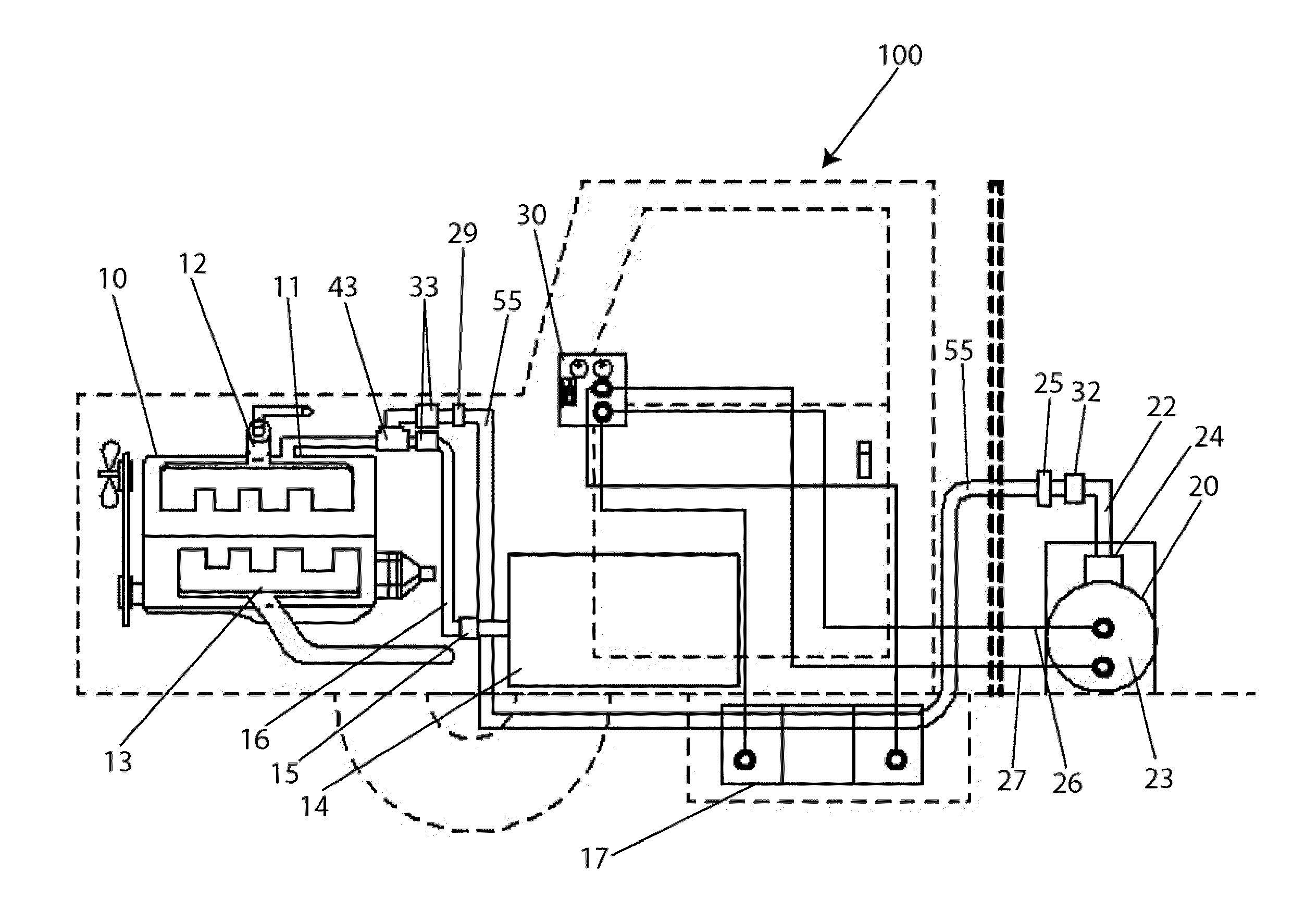
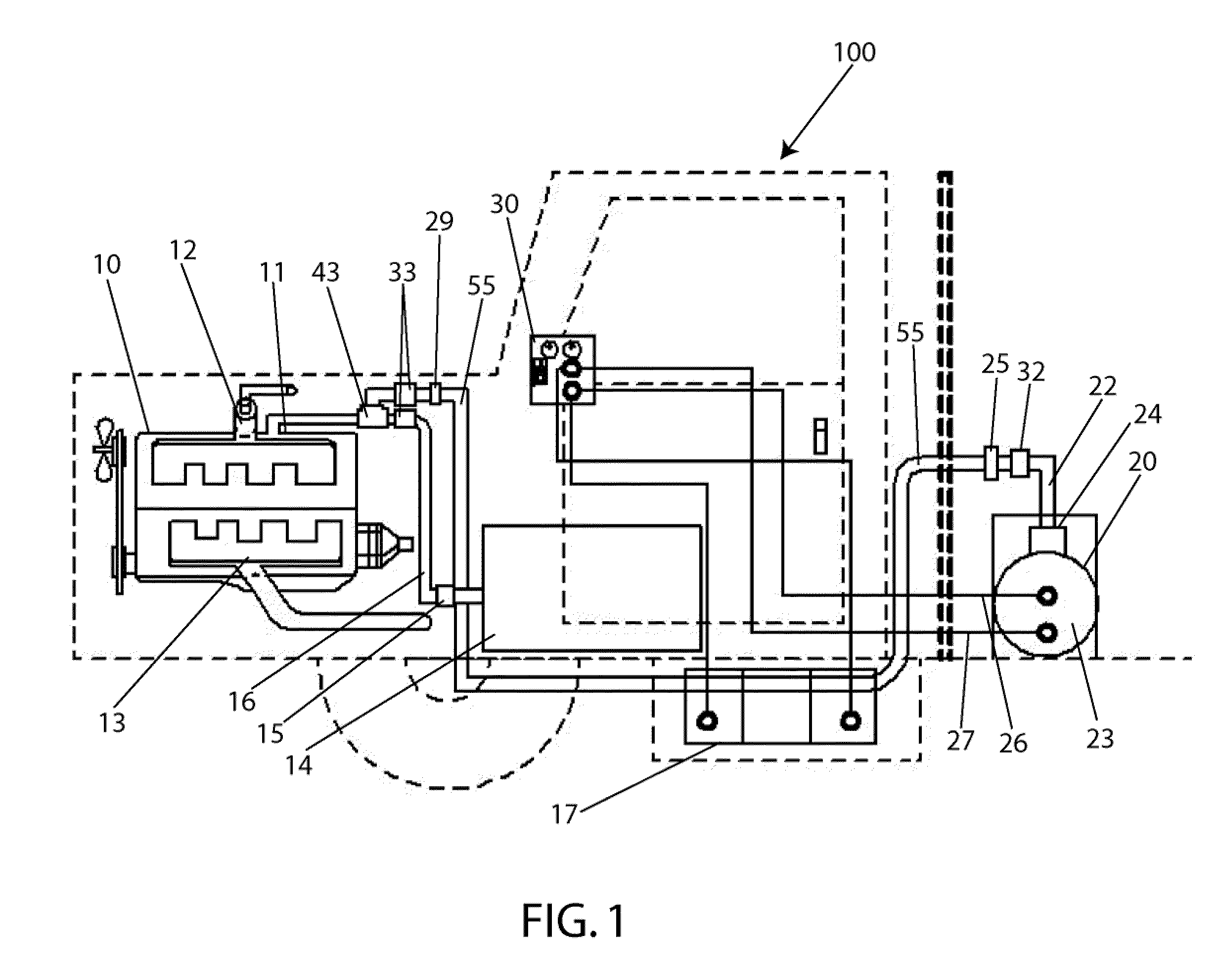
[0040]The present invention comprises an electrolysis system that generates and delivers hydrogen gas and oxygen gas to an internal combustion engine. Electrolysis is a well known process whereby an electrical current is passed through a water-based electrolyte solution. The electrical current splits the water molecules in the solution releasing hydrogen gas and oxygen gas. In the present invention, the hydrogen gas and oxygen gas are pressurized before being injected into the fuel line of an internal combustion engine to enhance its performance while reducing the emissions of toxic substances.

[0041]Application of the present invention is within vehicles that are powered by an internal combustion engine. This invention may be used with ...


PUM

PropertyMeasurementUnit
thickaaaaaaaaaa
thickaaaaaaaaaa
pressureaaaaaaaaaa

Abstract

Internal combustion engines operate by igniting a mixture of liquid fuel and air inside its combustion chamber. The energy from the ignition is converted to mechanical energy that is used to power a vehicle. Research indicates that adding hydrogen gas into the combustion chamber improves the efficiency of the engine. The present invention is an electrolysis system that produces hydrogen and oxygen gases and injects them into the fuel line of the engine to create a mixture of the gases and the liquid fuel that is subsequently introduced into the combustion chamber for ignition. The operating temperature of the engine is lower if the gases are injected into the fuel line rather than directly into the combustion chamber.

Description

BACKGROUND OF INVENTION[0001]1. Field of Invention[0002]The present invention is related to an apparatus and method of improving the fuel efficiency of an internal combustion engine, while improving the engine efficiency and reducing at least one toxic by-product from its combustion, and in particular, to an apparatus and method of hydrolyzing water into a mixture comprising hydrogen gas and oxygen gas to be mixed with the liquid fuel used in an internal combustion engine.[0003]2. Description of Prior Art[0004]The efficiency of internal combustion engines has improved significantly over the last few years while reducing toxic emissions. However, government regulations continue to force engine manufacturers to constantly seek improvements. This has spurred development of alternate fuel technologies such as electric engines, natural gas and propane fueled engines, hydrogen cell engines, and the like. While a number of these technologies are promising, some are still a long way from co...

Claims


Application Information

Patent Timeline
Patent Type & Authority Applications(United States)
IPC IPC(8): F02B43/08C25B9/00C25B1/02C25B9/17
CPCC25B9/06C25B9/063Y02T10/121F02B2043/106F02M25/12C25B15/00Y02T10/12C25B11/036C25B9/17
Inventor NOWICKI, RICHARDHERZSTOCK, JAMES J.SPURGIN, BLAKEDRAGAN, JOSEPH
Owner NOWICKI RICHARD
Why Eureka
Try Eureka