
Radar apparatus

a technology of radar and apparatus, applied in the field of radar devices, can solve the problems of inability to recognize the level of the reflected wave correctly, inability to search high-resolution with a radar wave having a narrow pulse width, and inability to interfere with other radar devices. , to achieve the effect of suppressing the level change of the receive signal and high-resolution search

Inactive Publication Date: 2006-08-24
ANRITSU CORP +1
View PDF9 Cites 29 Cited by
  • Summary
  • Abstract
  • Description
  • Claims
  • Application Information

AI Technical Summary

Benefits of technology

[0016] Accordingly, it is an object of this invention to solve the aforementioned problems and provide a radar device capable of correctly searching the surrounding environment with a high resolution.
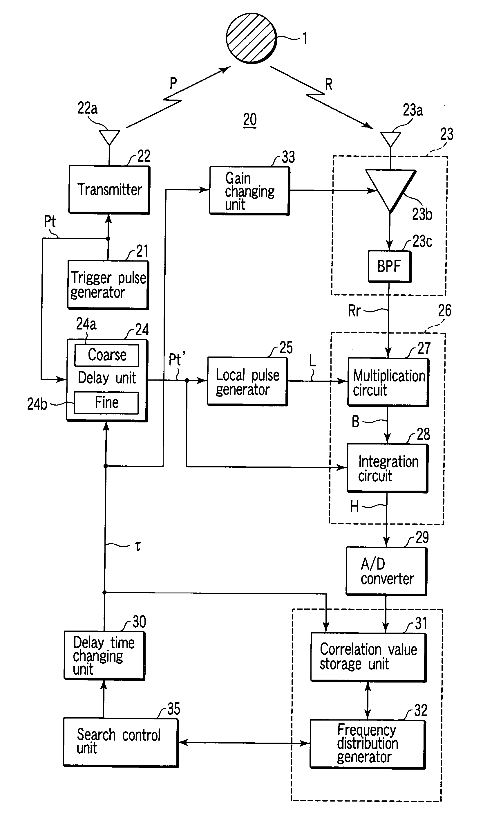
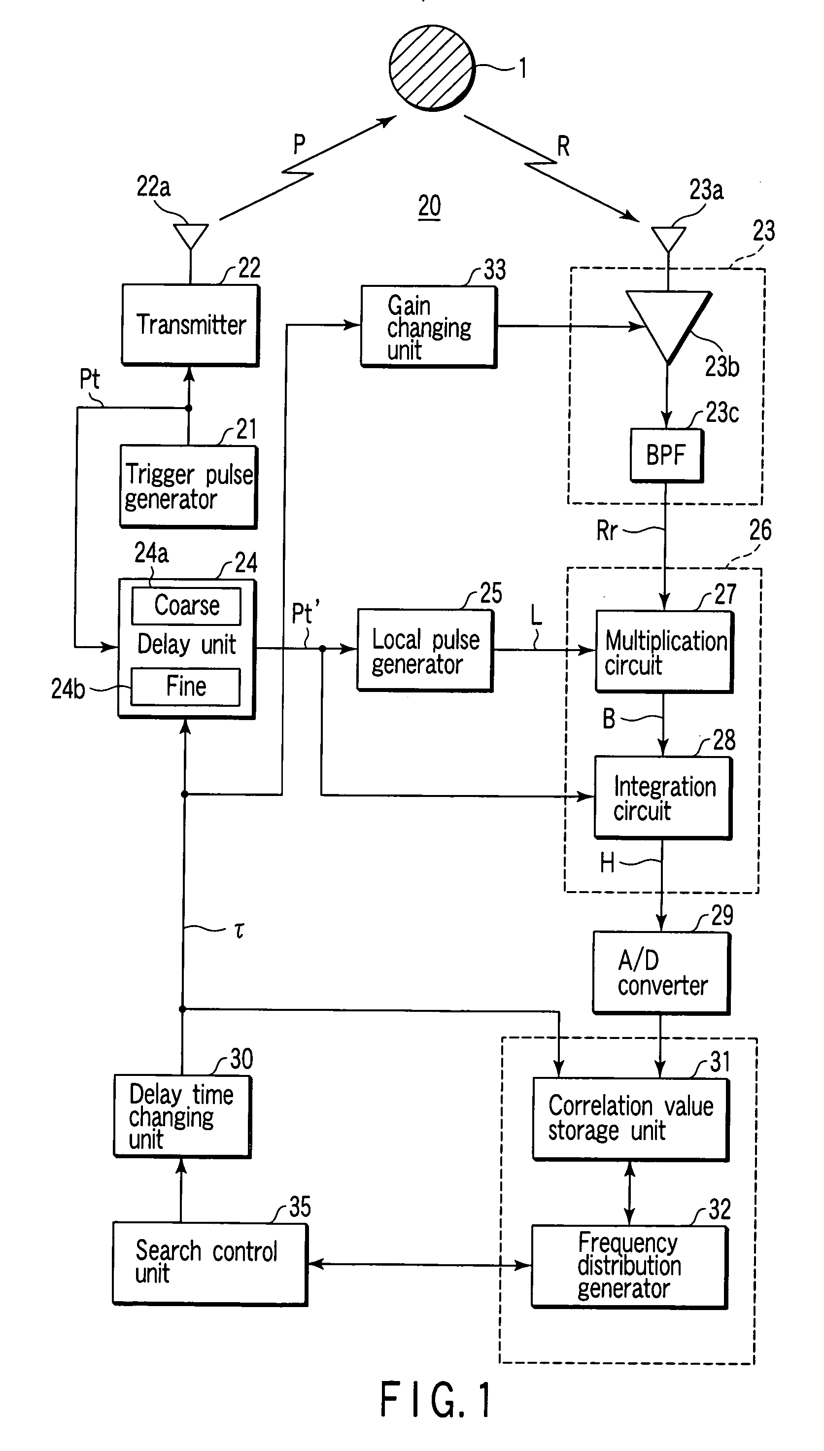
[0028] In order to achieve the above object, according to a second aspect of the present invention, there is provided a radar device according to the first aspect, wherein the receiver is configured to change a receiving gain against the reflected wave, the radar device further comprising a gain changing unit which variably controls the receiving gain of the receiver in accordance with the delay time changed by the delay time changing unit and suppresses a change in an output level of the receive signal due to a difference in the delay time.
[0061] Specifically, in the radar device according to the aforementioned aspects of the invention, unlike in the conventional radar device, the receive signal is not detected by a diode. Even a short-range radar device using a radar wave of a narrow pulse width, therefore, can grasp the strength of the reflected wave correctly from the frequency distribution of the strength correlation value against the delay time, thereby making a high-resolution search possible.
[0062] Also, in the radar device according to the aforementioned aspects of the invention, the receiving gain of the receiver against the reflected wave is variably controlled in accordance with the variable delay time thereby to suppress the level change of the receive signal with the difference in delay time.
[0063] As a result, the radar device according to the aforementioned aspects of the invention can prevent a signal of an excessively large level from being input to the correlation detection section and thus can detect the correlation value correctly within the proper operation range.

Problems solved by technology

It is basically unavoidable that the personal short-range radar device interferes with other radar devices.
The response rate of the diode detection circuit comprising the detector 14 described above, however, is at most about 100 nsec, and cannot correctly reflect the strength of the reflected wave R having a pulse as narrow as not more than 1 nsec as described above, thereby posing the problem that a high-resolution search with a radar wave having a narrow pulse width is impossible.
The conventional gain control method of the feedback type cannot follow this sharp change and may be unable to recognize the level of the reflected wave correctly.

Method used


Image

  • Radar apparatus
  • Radar apparatus
  • Radar apparatus

Examples


Embodiment Construction

[0089] Embodiments of the invention are explained below with reference to the drawings.

[0090]FIG. 1 is a block diagram showing a configuration of a radar device 20 according to an embodiment of the invention used as a short-range radar device for on-vehicle application, blind persons and medical purposes.

[0091] The basic configuration of the radar device according to this invention, as shown in FIG. 1, comprises a trigger pulse generator 21 for generating trigger pulses of a predetermined width at predetermined time intervals, a transmitter 22 for emitting, into the intended search space, a radar wave having a predetermined frequency pulse-modulated by the trigger pulse from the trigger pulse generator 21, a receiver 23 for receiving a reflected wave of the radar wave emitted by the transmitter 22 and reflected and outputting a receive signal, a delay unit 24 for delaying the trigger pulse from the trigger pulse generator 21 for a predetermined delay time, a local pulse generator ...


PUM


Abstract

A transmitter emits into an intended search space a radar wave having a predetermined frequency pulse-modulated by a trigger pulse of a predetermined width. A receiver receives a reflected wave of the radar wave and outputs a receive signal. A local pulse generator outputs a local pulse signal having the predetermined frequency pulse-modulated by the trigger pulse delayed by the delay unit. A correlation value detector detects a strength correlation value between the receive signal and the local pulse signal. A delay time changing unit changes the delay time sequentially within a range of a predetermined period representing a generation period of the trigger pulse. A correlation value storage unit stores the strength correlation value detected for each delay time changed. A frequency distribution generator generates a frequency distribution of a stored correlation value against the delay time. A search control unit executes an analyzation for the intended search space based on a generated frequency distribution.

Description

TECHNICAL FIELD [0001] The present invention relates to a radar device, and in particular to a short-range radar device for on-vehicle application, blind persons and medical purposes employing a technique capable of searching the surrounding environment with a high resolution. BACKGROUND ART [0002] In the prior art, a pulse radar device is used to search for the position (distance to and direction of the object), size and motion of an object existing around the user as a short-range radar device for on-vehicle application, blind persons and medical purposes. [0003]FIG. 9 is a block diagram showing a configuration of the essential parts of a conventional pulse radar device 10. [0004] Specifically, in the pulse radar device 10, a trigger pulse generator 11 generates a trigger pulse Pt of a predetermined width periodically and outputs it to a transmitter 12. [0005] The transmitter 12 emits a radar wave P pulse-modulated by the trigger pulse Pt to an intended search space through a tran...

Claims


Application Information

Patent Timeline
IPC IPC(8): G01S13/10G01S7/285G01S7/292
CPCG01S7/285G01S7/2923G01S13/0209G01S13/103
Inventor UCHINO, MASAHARU
Owner ANRITSU CORP
Learn More