Inkjet-Recording-Head Flushing Method

a technology of inkjet recording head and nozzle, which is applied in the direction of printing, other printing apparatus, etc., can solve the problems of inability to recover the ink-ejection performance of the nozzle, the problem is more likely to occur in the direction of nozzles with smaller diameters, and the ink dries around the nozzle-opening surface in a considerably short time. , to achieve the effect of efficiently recovering the ink-ejection performance, efficiently removing the ink

Active Publication Date: 2006-08-24
BROTHER KOGYO KK
View PDF8 Cites 15 Cited by
  • Summary
  • Abstract
  • Description
  • Claims
  • Application Information

AI Technical Summary

Benefits of technology

[0009] It is therefore an object of the present invention to solve at least one of the above-indicated problems. It is another object of the present invention to provide a flushing method that can efficiently recover an ink-ejection performance of at least one ink-ejection nozzle that ejects an ink that may contain a pigment.
[0010] The above objects may be achieved by the present invention according to which there is provided a method of flushing a nozzle of an inkjet recording head so as to recover an ink-ejection performance of the nozzle. The nozzle ejects, in a recording mode of the inkjet recording head, a plurality of droplets of an ink to record dot images, such that each of the droplets has an arbitrary one of a plurality of volumes. The flushing method comprises causing the inkjet recording head to perform, for a first time, a plurality of continuous flushing actions in each of which the nozzle attempts to eject a droplet of the ink whose volume is larger than a smallest volume of the plurality of volumes, and causing the inkjet recording head to repeat, at least one more time, the plurality of continuous flushing actions while interposing a pause time between each pair of consecutive times out of the first time and said at least one more time.
[0011] In the present flushing method, the nozzle of the inkjet recording head is flushed by performing the continuous flushing actions in each of which the nozzle attempts to eject a droplet of the ink whose volume is larger than the smallest volume of the plurality of volumes that are used in the recording mode. Therefore, bad ink whose viscosity has increased can be efficiently removed, with great forces, from the nozzle. In addition, since the ink droplets each having the large volume are continuously applied to the nozzle, the great forces are continuously applied to the bad ink so as to remove the ink. Thus, the bad ink can be efficiently expelled from the nozzle. Moreover, since the pause time or times is or are provided, the changes of the pressure applied to the meniscus formed by the surface tension of the ink at an open end of the nozzle, can be effectively reduced. Thus, the ink droplets can be easily ejected from the nozzle. Furthermore, since the series of continuous flushing actions is repeated one or more times, the bad ink can be removed with high reliability. Consequently the time duration needed to carry out the flushing operation can be shortened, and the amount of consumption of the ink can be reduced, so that the ink-ejection performance of the nozzle can be efficiently recovered to its normal condition. In particular, in the case where the ink is a pigment ink containing a pigment, the interposition of the above-indicated pause time or times leads to dispersing effectively the pigment component whose concentration has increased around a nozzle-opening surface of the inkjet recording head, so that the ink droplets can be easily ejected from the nozzle.

Problems solved by technology

However, in the case where a pigment ink is used, if a recording head is kept, when being not in use, such that a nozzle-opening surface thereof in which a nozzle opens is covered with a cap, the ink dries around the nozzle-opening surface in a considerably short time.
In this case, an ink-ejection performance of the nozzle cannot be recovered unless it is subjected to a long flushing operation in which it attempts to eject a great number of ink droplets.
This problem is more likely to occur to nozzles having smaller diameters.
However, the long flushing operation wastes a large volume of the pigment ink 98 and needs a long operation time.
In addition, if the long flushing operation is carried out in a low-temperature environment, the nozzle-opening surface 99a of the inkjet recording head 99 is likely to wet, and may even suck air bubbles to fail to eject ink droplets.

Method used


Image

  • Inkjet-Recording-Head Flushing Method
  • Inkjet-Recording-Head Flushing Method
  • Inkjet-Recording-Head Flushing Method

Examples


Embodiment Construction

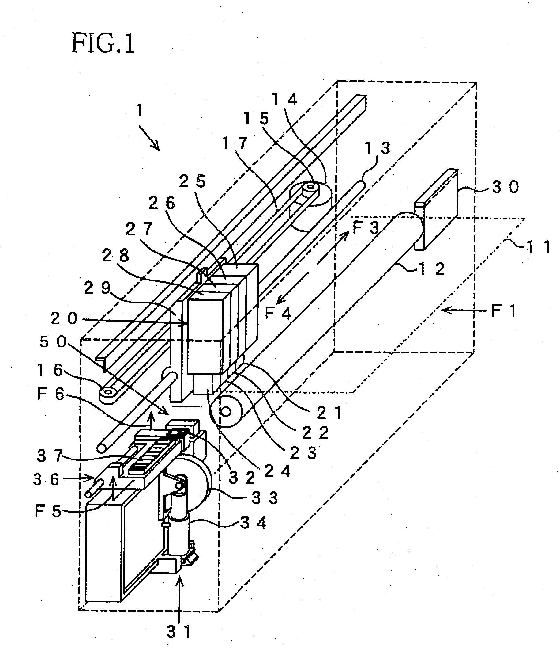
[0027]FIG. 1 shows a relevant portion of an inner construction of an inkjet printer 1 as a portion of an inkjet recording system that carries out a flushing method embodying the present invention. The following description relates to a piezoelectric-type inkjet printer 1 in which a piezoelectric effect of a piezoelectric element is utilized to eject droplets of ink, but the principle of the present invention is applicable to other sorts of inkjet recording apparatuses. Hereinafter, the inkjet printer 1 will be simply referred to as the printer 1.

[0028]1>

[0029] The printer 1 includes a platen roller 12 that feeds a recording sheet 11 as a sort of recording medium that is fed in a direction indicated by arrow, F1, in FIG. 1; a carriage-support axis member 13 that extends parallel to an axis line of the platen roller 12; and a carriage 29 which is supported by the axis member 13 and on which an inkjet recording head 20 is mounted. A carriage motor 14 is provided in the vicinity of one...


PUM


Abstract

A method of flushing a nozzle of an inkjet recording head so as to recover an ink-ejection performance of the nozzle. The nozzle ejects, in a recording mode of the inkjet recording head, a plurality of droplets of an ink to record dot images, such that each of the droplets has an arbitrary one of a plurality of volumes. The flushing method includes causing the inkjet recording head to perform, for a first time, a plurality of continuous flushing actions in each of which the nozzle attempts to eject a droplet of the ink whose volume is larger than a smallest volume of the plurality of volumes, and causing the inkjet recording head to repeat, at least one more time, the plurality of continuous flushing actions while interposing a pause time between each pair of consecutive times out of the first time and said at least one more time.

Description

[0001] The present application is based on Japanese Patent Application No. 2005-048516 filed on Feb. 24, 2005, the contents of which are incorporated herein by reference. BACKGROUND OF THE INVENTION [0002] 1. Field of the Invention [0003] The present invention relates to a method of flushing a nozzle of an inkjet recording head of an inkjet recording apparatus that ejects droplets of an ink containing a pigment toward a recording medium to record an image thereon, by ejecting, from the nozzle, droplets of the ink to recover an ink-ejection performance of the nozzle. [0004] 2. Discussion of Related Art [0005] A conventional inkjet recording apparatus has such a problem that a nozzle of an inkjet recording head thereof may fail to eject normally droplets of ink because the ink dries around a nozzle-opening surface of the head or a viscosity of the ink increases in a low-temperature environment, i.e., because energy needed to eject the ink droplets increases because of the increased vi...

Claims


Application Information

Patent Timeline
Patent Type & Authority Applications(United States)
IPC IPC(8): B41J2/165
CPCB41J2/16526
Inventor ITO, MASAHARU
Owner BROTHER KOGYO KK
Why Eureka
Try Eureka