Clock Extracting Circuit

a clock and clock signal technology, applied in the direction of digital transmission, pulse automatic control, snow cleaning, etc., can solve the problems of inability to appropriately decode the original digital signal into the clock signal, inability to obtain the appropriate clock signal, and inability to perform the appropriate decoding process or the lik

Inactive Publication Date: 2006-08-24
SANYO ELECTRIC CO LTD
View PDF2 Cites 19 Cited by
  • Summary
  • Abstract
  • Description
  • Claims
  • Application Information

AI Technical Summary

Problems solved by technology

If an edge of the received encoded signal coincides with an edge of the clock signal thus violating the setup/hold time, the original digital signal cannot be appropriately decoded into with the clock signal.
Moreover, where as the bit rate becomes higher, the pulse width of the clock signal needs to be

Method used


Image

  • Clock Extracting Circuit
  • Clock Extracting Circuit
  • Clock Extracting Circuit

Examples


Embodiment Construction

[0032] At least the following matters will be made clear by the explanation in the present specification and the description of the accompanying drawings.

==Configuration of Differential Bi-phase Decoder==

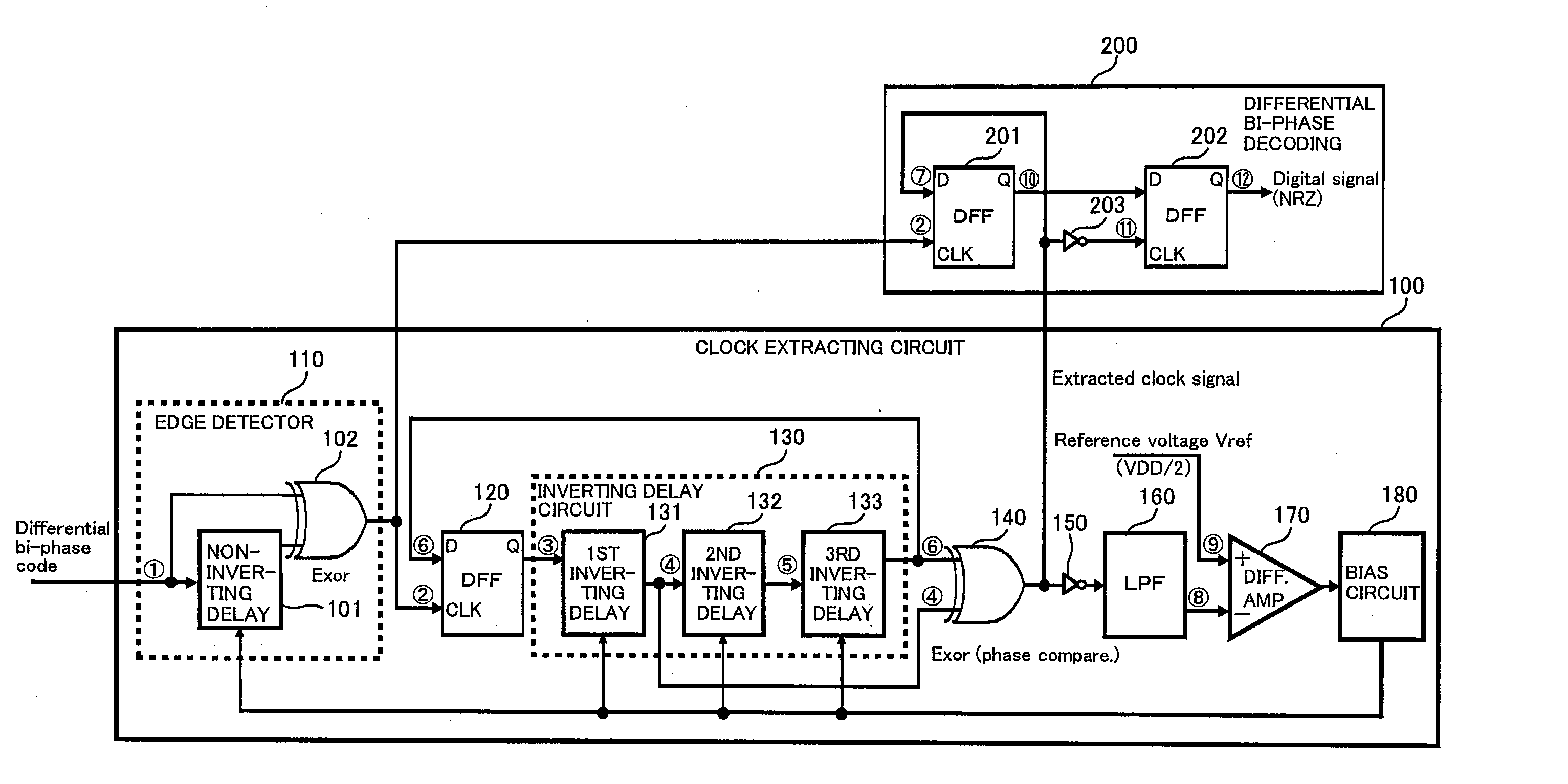
[0033]FIG. 1 is a diagram illustrating the configuration of a differential bi-phase decoder having a clock extracting circuit according to an implementation of the present invention. The differential bi-phase decoder of FIG. 1 receives a differential bi-phase code signal (encoded signal) into which a digital signal of a predetermined bit rate that is subject to transmission has been differential-bi-phase-encoded based on a clock signal, and decodes the received differential bi-phase code. Let r be the bit rate (bps) of the digital signal, then the frequency of the clock signal is expressed as “in (a natural number)×r (Hz)”. Hereinafter, “n=1” is assumed.

[0034] The differential bi-phase decoder of FIG. 1 comprises a clock extracting circuit 100 that extracts a clock signal from di...


PUM


Abstract

A clock extracting circuit for receiving an encoded signal and for extracting a clock signal from the encoded signal. The circuit comprises an edge detector that detects rising and falling edges of the encoded signal and produces edge detection pulses indicating the edges being detected; a mask signal generator producing a mask signal which is inverted in response to the edge detection pulses, which are produced one for each period of the received encoded signal, on the basis of the edge detection pulses; a mask signal delay section delaying the mask signal by a delay time controllable and outputting the delayed mask signal; a clock generator producing the clock signal on the basis of edges of the delayed mask signal; and a delay controller that controls the delay time of the mask signal delay section so as to set a duty ratio of the produced clock signal to a predetermined value.

Description

CROSS-REFERENCE TO RELATED APPLICATIONS [0001] The present application claims priority from Japanese Patent Application No. 2005-26715 filed on Feb. 2, 2005, which is herein incorporated by reference. BACKGROUND OF THE INVENTION [0002] 1. Field of the Invention [0003] The present invention relates to a clock extracting circuit. [0004] 2. Description of the Related Art [0005] Through communication networks such as LANs in offices and vehicle-mounted networks, digital signals are transmitted between apparatuses in the form of signals of various formats. Communication networks are beginning to be used to connect various digital apparatuses other than computers as well as being used to connect computers and their peripherals. An example thereof is vehicle-mounted networks and, for example, a MOST (Media Oriented Systems Transport) system has been proposed as a standard for vehicle-mounted networks. In the MOST system, a ring-like vehicle-mounted network is configured, and various appara...

Claims


Application Information

Patent Timeline
IPC IPC(8): H04L7/02
CPCH03L7/0812H04L7/0066H04L7/0087H04L7/033H04L25/4904H03L7/0814E01H5/066E01H5/067
Inventor SUZUKI, HIROHISAHASEGAWA, KAZUOAKAMA, EIJI
Owner SANYO ELECTRIC CO LTD
Why Eureka
Try Eureka