Robust service delivery node and method therefor

a node and service technology, applied in the field of optical networks, can solve the problems of a relatively small number of users, network equipment used to support metro and access applications is comparatively less robust and less complex than core network equipment, and the data rate and wavelengths are typically employed in core networks

Inactive Publication Date: 2006-08-24
POSITRON NETWORKS PNI
View PDF34 Cites 67 Cited by
  • Summary
  • Abstract
  • Description
  • Claims
  • Application Information

AI Technical Summary

Benefits of technology

[0015] the switch being responsive to the first control signal and having a first state and a second state such that in the first state an optical signal propagating to the first optical port propagates to the at least an optical port and

Problems solved by technology

The metro and access networks are not typically equipped to handle the high data rates and large numbers of wavelengths typically employed in core networks.
Additionally, these networks service a relatively small number of users.
Consequently, the designers of the metro and access networks are typically very price conscious and, as such, the equipment used to support metro and access applications is comparatively less robust and less complex than core network equipment.
Unfortunately, these objectives conflict as inexpensive components typically do not provide low mean times between failure.
Clearly, this represents a problem i

Method used


Image

  • Robust service delivery node and method therefor
  • Robust service delivery node and method therefor
  • Robust service delivery node and method therefor

Examples


first embodiment

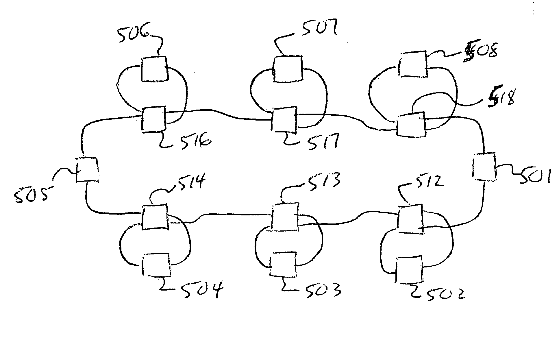
[0046] Referring to FIG. 5, a Sonet ring 500 according to the invention is shown. The Sonet ring comprises nodes 501 to 508. In this system the operation of nodes 501 and 505 is considered critical whereas the operation of nodes 502 to 504 and 506 to 508 are not considered critical. Each of nodes that are not considered critical have an optical cross connect switch 512 to 514 and 516 to 518 as described with reference to FIG. 4a and FIG. 4b optically coupled thereto. Those nodes that are considered critical feature independent electrical power sources. The optical cross connect switches act to ensure that nodes that are not considered critical are bypassed when they are not receiving power. Specifically, optical cross connect switch 512 is set to divert optical signals to node 502 when the optical cross connect switch 512 is receiving sufficient electrical energy. The electrical energy provided to the optical cross connect switch 512 is provided by the node 502. Thus, when node 502 ...

second embodiment

[0050] Referring to FIG. 7, a unidirectional path switch ring (UPSR) network 700 according to the invention is shown having nodes 701 to 704 a first ring 709a and a second ring 709b. Each of the nodes is supported by two cross connect switches 711a and b to 714a and b. The switches are coupled to their associated nodes in a fashion that causes them to change state thereby preventing optical signals from being provided to their associated node when the node does not receive a predetermined amount of power. Similarly, when an appropriate level of power is provided to the node the switches maintain another optical path that supports optical communication between the node and the rings 709a and 709b.

[0051] A person of skill in the art will appreciate that a wide variety of different switching optical network topologies are also supported according to the invention. For example, the network shown in FIG. 5 is consistent with a single ring bi-directional line switched ring (BLSR) network...

fourth embodiment

[0054] Referring to FIG. 10, a schematic diagram of a mesh network 1000 according to the invention is shown. The mesh network 1000 comprises nodes 1001, 1002, 1003 and 1004, data links 1005, and optical switches 1010 and 1011. The optical switches 1010 and 1011 support an optical connection from an input port 1010a and 1011a to any one of three corresponding output ports 1010b, 1010c, 1010d, 1011b, 1011c and, 1011d. In this embodiment of the invention the switches 1010 and 1011 are synchronized such that the switches are maintained in a similar state. Thus, when switch 1010 is providing an optical connection from 1010a to 1010b then switch 1011 is set to provide an optical connection from 1011a to 1011b. The nodes of the mesh network support add-drop functionality. In use, when it is desired to provided data from node 1001 to node 1003 a data path is established from node 1001 to node 1003 via node 1002. If node 1002 goes into a bypass-mode then a new data path is established in whi...


PUM


Abstract

In an optical network some optical nodes are fitted with optical switches. The optical switches support the optical coupling and decoupling of the optical nodes and the remainder of the optical network. Electrical power supply failures to a node result in the node being optically decoupled from the remainder of the optical network thereby allowing the remaining nodes to continue normal operation.

Description

[0001] This application claims benefit from the following U.S. Provisional Applications: No. 60 / 654,467 filed Feb. 22, 2005; No. 60 / 654,468 filed Feb. 22, 2006 and No. 60 / 654,469 filed Feb. 22, 2005, the entire contents of which are incorporated herein by reference.FIELD OF THE INVENTION [0002] The invention relates to optical networks. More specifically, the invention relates to a system for automatically bypassing those nodes of an optical network that are not suitable for receiving signals from other nodes. BACKGROUND OF THE INVENTION [0003] Use of the Internet has grown dramatically and to that end, core networks featuring long haul high bandwidth fiber optic equipment have been deployed to help support data traffic on the Internet. Internet traffic and other data services are eventually routed to end users via metro and access networks. The metro and access networks are not typically equipped to handle the high data rates and large numbers of wavelengths typically employed in c...

Claims


Application Information

Patent Timeline
IPC IPC(8): H04J14/02
CPCH04B10/27H04J3/085H04J3/14H04Q11/0062H04Q2011/0081
Inventor NIKOLOPOULOS, JOHNFRANK, SILVO J.
Owner POSITRON NETWORKS PNI
Why Eureka
Try Eureka