Spectacle lens manufacturing method and spectacle lens manufacturing system

a manufacturing method and technology of spectacle lenses, applied in the direction of electrical programme control, instruments, programme control, etc., can solve the problems of large number of semi-finished lens blanks in stock, the above-described conventional spectacle lens manufacturing system has problems, and is considered to be theoretically unavoidable, so as to reduce waste, reduce production costs, and reduce production costs

Inactive Publication Date: 2006-08-24
HOYA CORP
View PDF5 Cites 38 Cited by
  • Summary
  • Abstract
  • Description
  • Claims
  • Application Information

AI Technical Summary

Benefits of technology

[0024] One of embodiments according to the present invention is characterized in that a circular lens forming step is structured to form a curved surface shape on a plastic material in a manner that a geometric center of an edge shape positions at a center of the plastic material. This characteristic has a meaning as below. Specifically, conventionally, in the case where a lens member before processing of being shaped into the edge shape (an outer contour of this lens member is not necessary to be a circle) is, for example, a circular lens having substantially a circular outer contour, a curved surface shape is formed so that an optical center or a prism measurement point positions at the geometric center of the circle to thereby serve as an optical surface. This has been considered to be logically necessary for the convenience of a curve generator performing a conventional curved surface formation, and holding the lens when edging. To the contrary, one of the embodiments in the present invention is the one revoking such common practice. Specifically, first, it is conceived that the optical center or prism measurement point does not necessary position at the geometric center of the circle when the holding technique at the time of the processing is devised. Next, it is conceived that, when an attention is paid to the point that the processing is performed up to form the edge shape at the manufacturing side, there is no need to process the circular lens to form a curved surface shape in which the optical center or prism measurement point positions at the geometric center of the circle, and a processing to form a curved surface shape in which the geometric center of the edge matches with the geometric center of the circular lens has no problem. In other words, it is to form a circular lens in which the optical center or prism measurement point positions at a position different from the geometric center of the circle. With this, it becomes possible to define an edge shape in a circular lens having an outside diameter extremely close to the maximum outside diameter of the edge shape, allowing a substantial reduction in waste as compared to a conventional method. According to the other embodiment of the present invention, in order to correspond to various types of eccentric quantities, semi-finished lens blanks or lens blanks having optical centers different from their geometric centers are prepared in advance, so that a speedy manufacturing is enabled. Further, the processing to form a curved surface is performed to the lens blank as a start, requiring no shaping die of a high profile irregularity. According to still another embodiment of the present invention, the processing by a curve generator is allowed without changing conventional processing method largely.
[0025] Further more, according to still another embodiment, the types of lens blank to be prepared in advance can be reduced in number.

Problems solved by technology

It is found that the above-described conventional spectacle lens manufacturing system has problems as below.
Meanwhile, however, this system has a problem that a great number of semi-finished lens blanks should be in stock.
This has been considered to be theoretically unavoidable as long as the eccentric quantity exists.
However, the shift of the geometric center of the edge shape by the eccentric quantity with respect to the center of the circular lens causes a problem as below.

Method used


Image

  • Spectacle lens manufacturing method and spectacle lens manufacturing system
  • Spectacle lens manufacturing method and spectacle lens manufacturing system
  • Spectacle lens manufacturing method and spectacle lens manufacturing system

Examples


Embodiment Construction

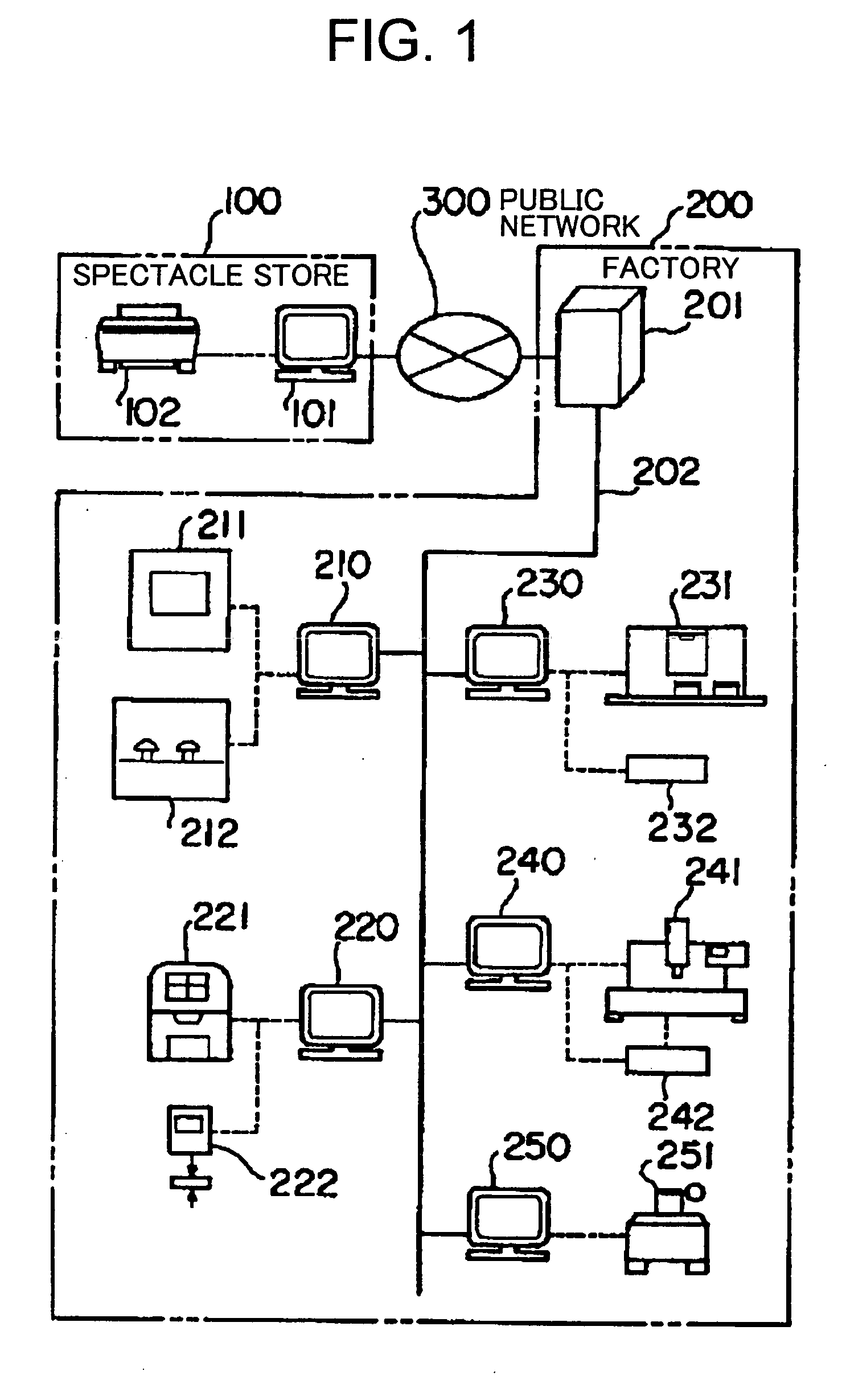
[0026] Hereinafter, a spectacle lens manufacturing method and a spectacle lens manufacturing system according to an embodiment of the present invention will be described based on the drawings. Note that the spectacle lens manufacturing method related to the embodiment is used in the spectacle lens manufacturing system related to the embodiment, so that the description will be given by being included in the description of the spectacle lens manufacturing system. FIG. 1 is a view showing an entire configuration of the spectacle lens manufacturing system according to the embodiment. In this spectacle lens manufacturing system, an order terminal 101 and a spectacle lens design device 201 are connected via a network 300. The order terminal 101 is set at a spectacle store 100 as an orderer. The spectacle lens design device 201 is set at a factory 200 as a spectacle manufacturer side. At the factory 200 side, a lens processing device is connected to the spectacle lens design device 201 via...


PUM

PropertyMeasurementUnit
diametersaaaaaaaaaa
diametersaaaaaaaaaa
diameteraaaaaaaaaa

Abstract

Aims to reduce the types of blanks such as a semi-finished lens blank, materials, and processing time. A spectacle lens design device 201 disposed at a factory 200 on a manufacturing side and a lens processing device connected thereto block an applicable semi-finished lens blank or lens blank so that a reference surface thereof tilts at a predetermined angle using a numerical-control curve generator based on order information sent from an order terminal 101 disposed at an spectacle store 100 on a order-placement side, and form both surfaces of a plastic material so that a geometric center of an edge shape positions at a center of a circle of a circular lens to thereby satisfy an optical specification of the spectacle lens-related to the order, and next, the circular lens is processed to have the edge shape of the spectacle lens-related to the order to thereby obtain the spectacle lens-related to the order.

Description

TECHNICAL FIELD [0001] The present invention relates to a spectacle lens manufacturing method and a spectacle lens manufacturing system manufacturing a spectacle lens based on order information including spectacle frame information, a prescription value, and layout information. BACKGROUND ART [0002] Generally, a spectacle lens is manufactured by a manufacturing side such as a lens maker based on order information obtained from an order-placement side such as a spectacle store, and provided to the order-placement side. In this case, there are two types for the lenses provided by the manufacturing side, namely one requiring an edging at the spectacle store and the others finished to be settable as it is to a frame without the need for the edging at the spectacle store. In the former case, the lens provided by the manufacturing side has optical surfaces of a curved surface shape satisfying an optical specification such as a diopter and the like on both the surfaces, while the outer sha...

Claims


Application Information

Patent Timeline
Patent Type & Authority Applications(United States)
IPC IPC(8): B24B51/00B24B1/00B24B7/00B24B29/00B24B9/14B24B13/00G05B19/418
CPCB24B9/148G05B2219/32024G05B2219/35097G05B2219/45157Y02P80/40
Inventor AKIYAMA, HISANORI
Owner HOYA CORP
Why Eureka
Try Eureka