
Method and apparatus for manufacturing a bag equipped with spouts

a manufacturing method and bag technology, applied in the field of methods and apparatus for manufacturing bags equipped with spouts, can solve the problems of increasing the number of steps required, increasing the cost and maintenance of cleaning, etc., and achieving the effect of preventing bending or curvature of the bag surface, simple mechanism, and not increasing the number of steps

Inactive Publication Date: 2006-08-24
TOYO JIDOKI CO LTD
View PDF4 Cites 16 Cited by
  • Summary
  • Abstract
  • Description
  • Claims
  • Application Information

AI Technical Summary

Benefits of technology

[0011] The object of the present invention is to provide a bag manufacturing method that increases the bag manufacturing performance and at the same time to eliminate unreliability in positioning of the spout(s) inserted in the mouth(s) of a bag (called “bag mouth(s)) and in addition to provide a bag manufacturing apparatus which is more compact and simpler in size and structure.
[0045] The portions near both shoulders of the top edge of the above-described bag are unsealed in a continuous manner to both shoulders, and at the spout inserting position at least one of the portions including such unsealed portions is opened as the bag mouth(s); accordingly, the bag can be opened in a larger size than the formed mouth(s) is opened, and insertion of even a large-size spout(s) becomes easy.

Problems solved by technology

Therefore, such a halting position makes the step that controls the speed, and the problem arises that improving the performance of the apparatus (pieces / minute) is difficult.
H10-323920, the many container holding parts are packed in with their many respective mechanisms, so the structure of the container holding part is complicated, causing problems of increased cost and issues regarding cleaning, maintenance, etc.
Therefore, the number of steps required increases, and the number of halting positions increases; and in addition, the apparatus itself becomes large size-wise.
Thus, the problem is that the bag carrying stand mechanism is complicated.

Method used


Image

  • Method and apparatus for manufacturing a bag equipped with spouts
  • Method and apparatus for manufacturing a bag equipped with spouts
  • Method and apparatus for manufacturing a bag equipped with spouts

Examples


Embodiment Construction

[0054] Below, the present invention will be described in detail with reference to FIGS. 1 through 8.

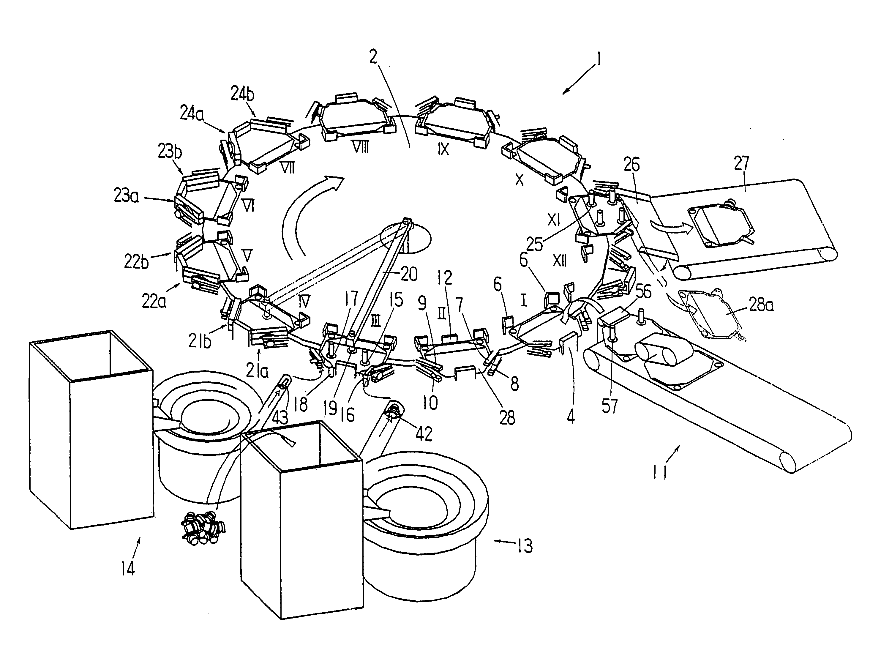
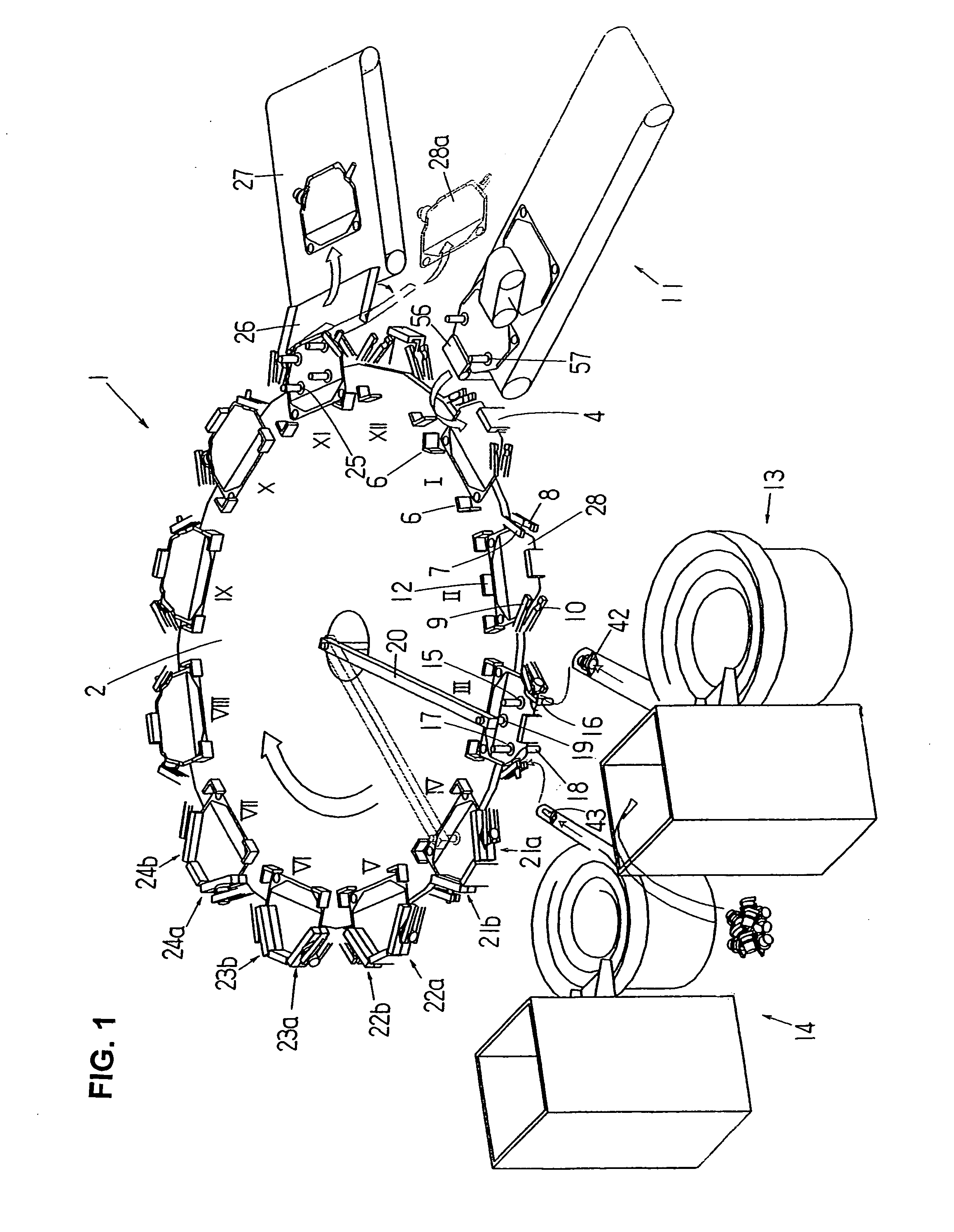
[0055] The apparatus for manufacturing a bag equipped with at least one spout is, as seen from FIG. 1, comprised of an intermittently rotating table-type spout inserting and sealing apparatus 1 and various devices that are provided at locations corresponding to the halting positions of the intermittently rotating table-type spout inserting and sealing apparatus 1.

[0056] The spout inserting and sealing apparatus 1 includes a table 2 that rotates intermittently and a bag-gripping device 3 (only an upper bag-gripping member 4 thereof is shown) that is disposed at each of the twelve (12) locations on the periphery of the table 2. A bag positioning device 5 (only bag positioning members 6 thereof is shown) and spout gripping members 7-10 that correspond to each bag-gripping device 3 are provided on the table 2.

[0057] The table 2 halts twelve (12) times in the course of one rotation. The...


PUM


Abstract

An intermittently rotating table-type apparatus for manufacturing a bag equipped with spout(s). The apparatus attaches spout(s) to at least one of the mouths of a bag that are at both shoulders of the bag. The mouth(s) of the bag is expanded by bag mouth suction cups, and the main body of the bag is expanded by main body suction cups; and then the spout(s) is inserted in the bag mouth(s), and the inserted spout(s) is held by spout gripping members. When the bag is moved by the rotation of the table, a suction cup arm that supplies suction air to the suction cup and the suction cup are moved to follow the movement of the bag; and after the sealing is made to the bag and spout(s), the arm and the suction cup return to their original positions.

Description

BACKGROUND OF THE INVENTION [0001] 1. Field of the Invention [0002] The present invention relates to a method and apparatus for manufacturing a bag equipped with a spout(s) by inserting a spout(s) in the mouth(s) of a bag and sealing the spout(s) and bag mouth(s) (including sealing of the opening part of the bag mouth(s)). [0003] 2. Description of the Related Art [0004] Japanese Patent Application Laid-Open (Kokai) No. H10-291509 discloses an apparatus in which the chain of a rotary apparatus is provided with a plurality of holding means and is intermittently rotated, spouts are supplied to the holding means and are transported along the movement path of the chain, and in the course of this movement the spout and bag are sealed, thus manufacturing a bag equipped with a spout; then steps are performed such as evacuating the bag interior and filling it with contents, etc. In the process of manufacturing a bag equipped with a spout, a halted bag with its bag mouth opened is moved horiz...

Claims


Application Information

Patent Timeline
Patent Type & Authority Applications(United States)
IPC IPC(8): B31B49/04B31B50/80B31B70/00
CPCB31B1/80B31B19/84B31B2201/287B31B2219/9054Y10S493/929B31B70/844B31B70/00B31B70/003B31B50/00B31B50/80
Inventor TSUTSUI, SHOJINAKAMOTO, KAKUE
Owner TOYO JIDOKI CO LTD
Learn More