Write barrier for data storage integrity

Inactive Publication Date: 2006-08-24
MICROSOFT TECH LICENSING LLC
View PDF5 Cites 36 Cited by
  • Summary
  • Abstract
  • Description
  • Claims
  • Application Information

AI Technical Summary

Benefits of technology

[0012] The subject invention is an efficient, backwards-compatible, purely client-driven implementation of write barriers without requiring any changes to the existing storage stack model of an operating system with an asynchronous I/O model. Additionally, the invention can be implemented in either user mode or kernel mode, which allows any application to benefit, if the application requires the performance of direct-I/O, for example. When employed

Problems solved by technology
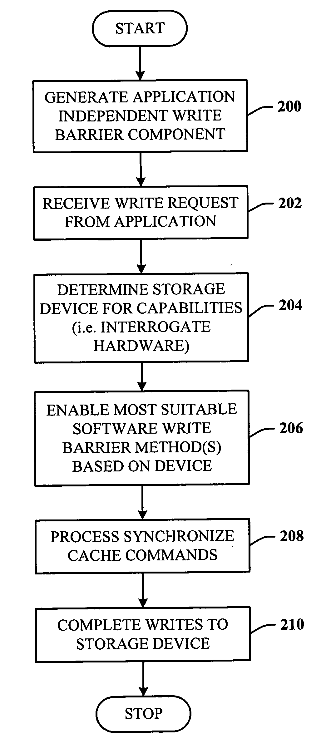
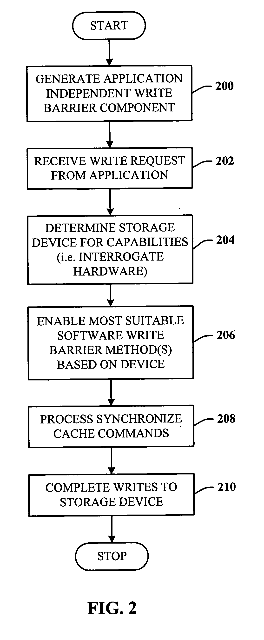
For example, open transactions must be committed to the transaction log before the file system structure is accessed; otherwise, a system fault could impact the file system integrity.
Unfortunately, data storage is a very difficult area in which to work due to multiple hardware “defects” (or design limitations), incorrect implementations, or purposeful ignorance of the drive specifications to meet market demands.
An example of this latter defect includes increasing performance (e.g., a 2% boost in a benchmark) at the expense of data integrity by providing onboard caching without considering the potential problems for ensuring data integrity at the storage media.
However, not all hardware storage devices support write-through capability.
However, the device does not support FUA.
Thus, in the translation that occurs for a write-through request in the storage stack for the ATA disk drive, the write-through semantics of the request are lost when communicating from the IDE driver to the hardware device.
Moreover, where the storage device includes an onboard cache, which is becoming increasingly commonplace, none of theses storage devices support selective flush of their hardware cache.
Thus, the request

Method used


Image

  • Write barrier for data storage integrity
  • Write barrier for data storage integrity
  • Write barrier for data storage integrity

Examples


Embodiment Construction

[0031] The invention is now described with reference to the drawings, wherein like reference numerals are used to refer to like elements throughout. In the following description, for purposes of explanation, numerous specific details are set forth in order to provide a thorough understanding of the subject invention. It may be evident, however, that the invention can be practiced without these specific details. In other instances, well-known structures and devices are shown in block diagram form in order to facilitate describing the invention.

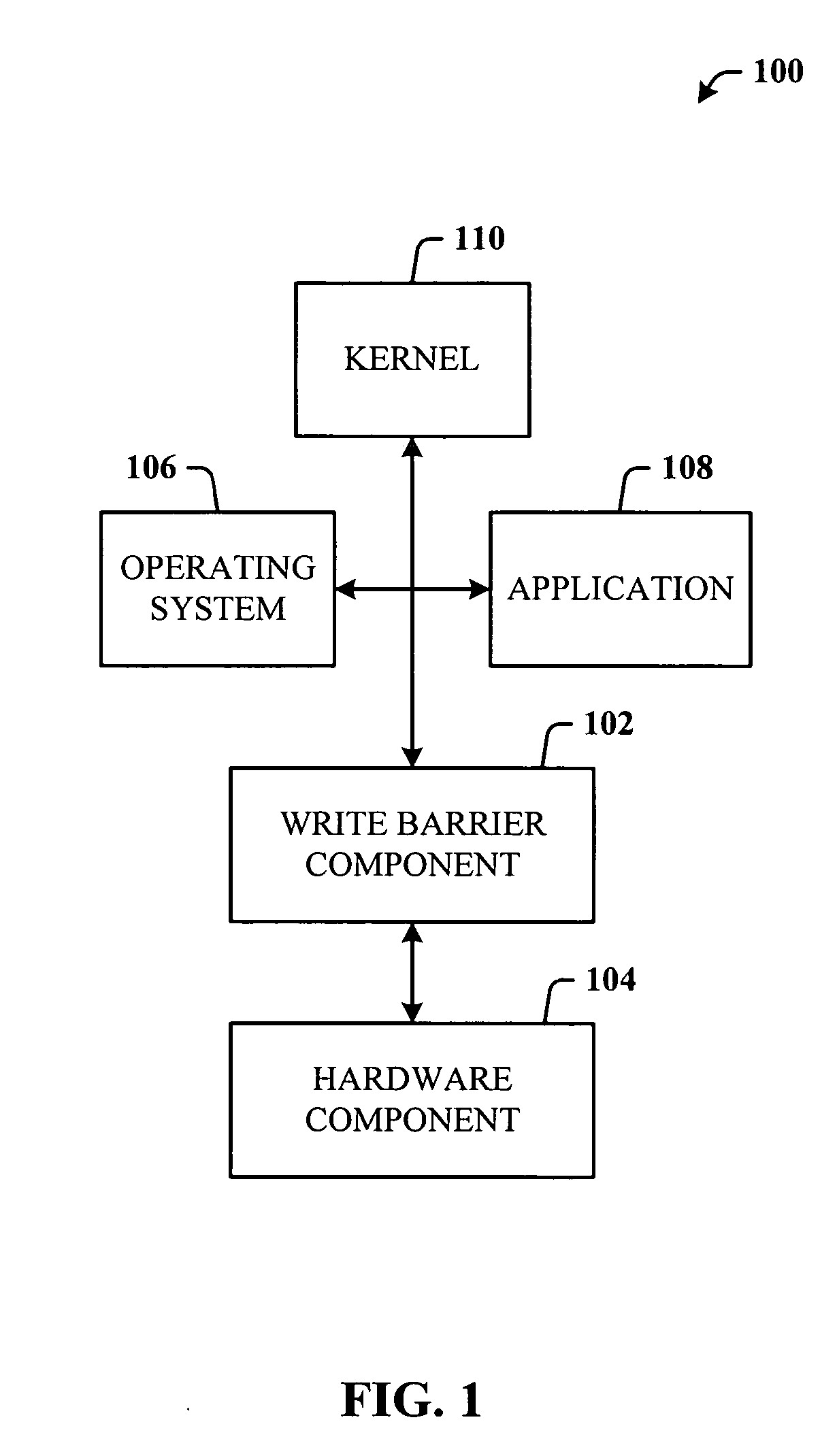
[0032] As used in this application, the terms “component” and “system” are intended to refer to a computer-related entity, either hardware, a combination of hardware and software, software, or software in execution. For example, a component can be, but is not limited to being, a process running on a processor, a hard disk drive, a plurality of drives (of optical and / or magnetic medium), a processor, an object, an executable, a thread of execut...


PUM


Abstract

A system that facilitates the storage of data using a write barrier. The system interfaces to a hardware component that stores data, and includes a write barrier component that dynamically employs instructions compatible with the hardware component to ensure data integrity during storage of the data. The write barrier component is independent of at least an operating system and an application and can operate in a least one of a user mode and a kernel mode. The write barrier component includes at least one of software instructions, routines, and methods, the selection of one or more of which is based on hardware data extracted from the hardware component. A selection component interrogates the hardware component for hardware data to facilitate selection of one or more instructions most suitable for interfacing to the hardware component. A coalescing component combines cache synchronization requests into a single set of instructions, which set is processed to flush a disk cache in one process.

Description

TECHNICAL FIELD [0001] This invention is related to techniques for ensuring data storage, and more specifically, to a write barrier mechanism for data storage integrity. BACKGROUND OF THE INVENTION [0002] Modern journaling file systems (e.g., NTFS) and specialized applications (e.g., SQL (Structured Query Language) databases) provide a backup and recovery capability, which requires an efficient mechanism to ensure that associated transactional logs (or any piece of data) are on the storage media for subsequent recovery (e.g., after a power outage). Before indexes on disk (e.g., magnetic media) are updated, the information about the changes is recorded in the transactional log. If a power or other system failure corrupts the indexes when being rewritten, the operating system can use the log to repair the indexes when the system is restarted. Thus, these systems and applications generally operate under strict regimes for ordering disk I / O operations. For example, open transactions mus...

Claims


Application Information

Patent Timeline
IPC IPC(8): G06F17/30G06F13/28
CPCG06F11/004G06F12/0804G06F12/0866G06F13/102
Inventor GABRYJELSKI, HENRY P.VARADARAJAN, KRISHNANWIELAND, PETER W.RAMANATHAN, RAJU
Owner MICROSOFT TECH LICENSING LLC
Why Eureka
Try Eureka