
Method and apparatus for verifying memory testing software

Active Publication Date: 2006-08-24
MARVELL ASIA PTE LTD
View PDF20 Cites 19 Cited by
  • Summary
  • Abstract
  • Description
  • Claims
  • Application Information

AI Technical Summary

Benefits of technology

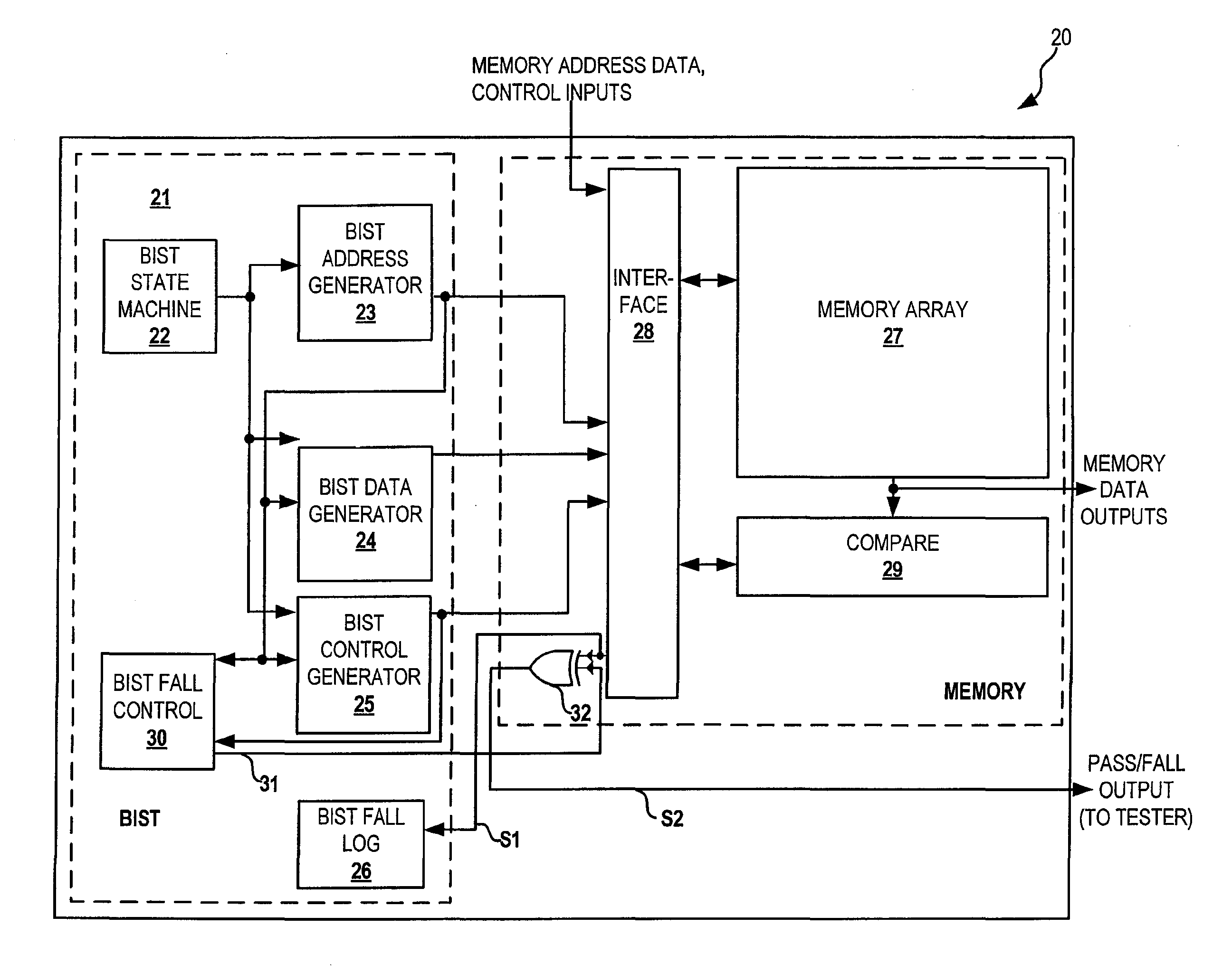
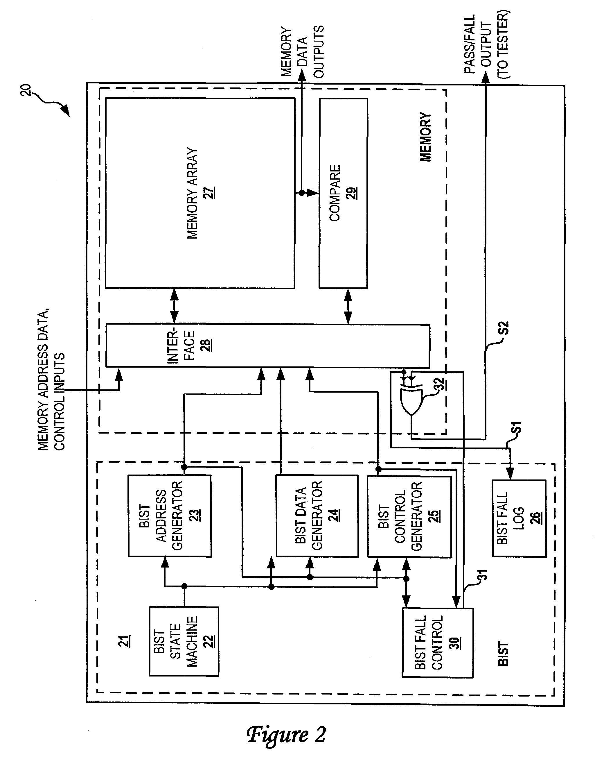
[0009] In accordance with a preferred embodiment of the present invention, a built-in self test (BIST) fail control function is utilized to generate multiple simulated memory fails at various predetermined locations within a memory array of a memory device. The memory array is then tested by a memory tester. Afterwards, a bit fail map is generated by the logical-to-physical mappin

Problems solved by technology

The major problem in memory testings lies upon the inability to verify whether or not the logical-to-physical mapping software is functioning correctly.
Also, the cycle delays from the time a memory fail occurred to the time the memory fail being detected are usually not accounted for.
In addition, during a cycle in which a memory tester observed the fail, test data are not corrected for cycle offsets due to counters (such as whether it starts at 0 or 1) and for any operations that take place before memory test begins (e.g., a “reset” operation).
With such methodology, however, only by physically observing multiple defects with high accuracies can any level of confidence be achieved.

Method used


Image

  • Method and apparatus for verifying memory testing software
  • Method and apparatus for verifying memory testing software
  • Method and apparatus for verifying memory testing software

Examples


Embodiment Construction

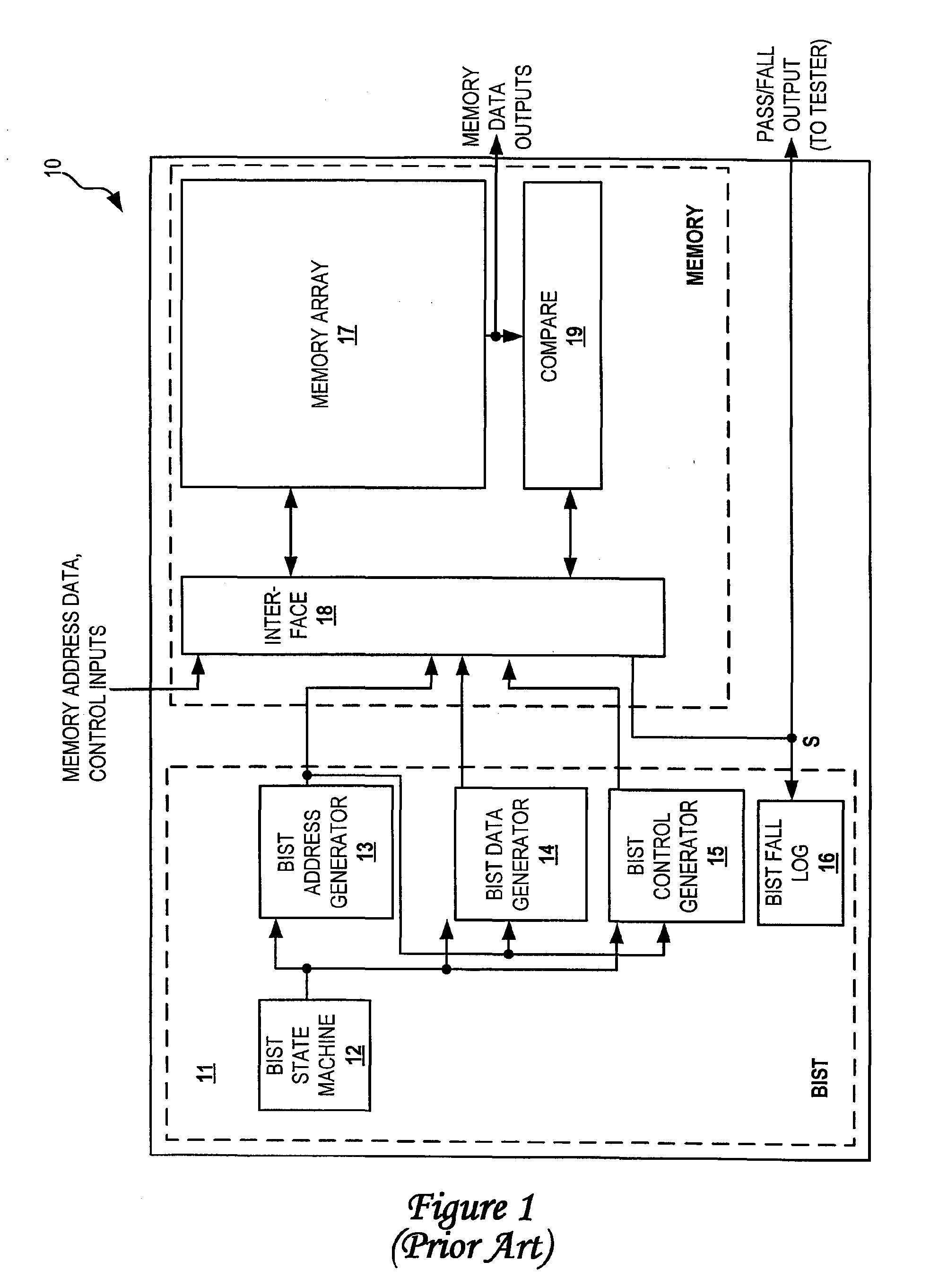
[0016] Referring now to the drawings and in particular to FIG. 1, there is illustrated a block diagram of a built-in self-test (BIST) configuration within a memory device, according to the prior art. As shown, a BIST 11 is coupled to a memory array 17 via an interface 18 within a memory device 10. BIST 11 includes a BIST state machine 12 for controlling a BIST address generator 13, a BIST data generator 14 and a BIST control generator 15. BIST 11 tests memory array 17 by performing a series of read and write operations on memory array 17 in sequences that are well-known to those skilled in the art. After comparing the expected data from BIST 11 to the actual data coming from memory array 17 from a read operation, a compare module 19 generates a pass / fail signal S to indicate whether or not there is a match. Pass / fail signal S is recorded in a BIST fail log 16. At the end of a BIST sequence, BIST fail log 16 can be used to determine if a memory fail occurred at any time during the BI...


PUM


Abstract

A method for verifying the accuracy of memory testing software is disclosed. A built-in self test (BIST) fail control function is utilized to generate multiple simulated memory fails at various predetermined locations within a memory array of a memory device. The memory array is then tested by a memory tester. Afterwards, a bit fail map is generated by the logical-to-physical mapping software based on all the memory fails indicated by the memory tester. The bit fail map provides all the fail memory locations derived by the logical-to-physical mapping software. The fail memory locations derived by the logical-to-physical mapping software are then compared to the predetermined memory locations to verify the accuracy of the logical-to-physical mapping software.

Description

BACKGROUND OF THE INVENTION [0001] 1. Technical Field [0002] The present invention relates to software tools in general, and, in particular, to a software tool for verifying memory testing software. Still more particularly, the present invention relates to a method and apparatus for verifying the accuracy of logical-to-physical mapping software. [0003] 2. Description of Related Art [0004] Conceptually speaking, diagnosing failures in a memory device is fairly straightforward. Basically, after a memory tester has detected a failure in a memory device, the logical address of the failed memory location is translated into a corresponding physical location within the memory device. Such translation is commonly known as a logical-to-physical translation and is typically performed by a logical-to-physical mapping software. Once the failed physical location of the memory device is known, different analyses can be performed. For example, photographic data of the memory device can be compared...

Claims


Application Information

Patent Timeline
IPC IPC(8): G01R31/28
CPCG11C29/12G11C29/56G11C2029/0405G11C2029/5604
Inventor JASINSKI, ERICOUELLETTE, MICHAEL RICHARDROWLAND, JEREMY PAUL
Owner MARVELL ASIA PTE LTD
Learn More