
Eureka
For R&D, Eureka makes reading and utilizing patents & technical documents easy.
Eureka AIR
Designed for self-driven R&D workflows. Generate viable solutions, solve complex R&D challenges, empower your innovation with AI.

Eureka Materials
Designed for material experts only. Revolutionize your material R&D, from search, analyze, to developing new materials.

TechResearch
Generate reliable direction feasibility study reports for your R&D in just a few steps.

TechSeek
Discover and master advanced knowledge NOW. Basics, ideas, possibilities, all at once.

TechMind
As an expert in R&D Theories, TechMind can generates customized viable solutions instantly.

TechRisk
Analyze your overall solution with one click, know your potential R&D risks in advance.

TechMonitor
Get weekly tech updates, stay abreast of the latest tech innovations and key insights.
Cell instance generating method
- Summary
- Abstract
- Description
- Claims
- Application Information
AI Technical Summary
Benefits of technology
Problems solved by technology
Method used
Image

Examples
embodiment 1
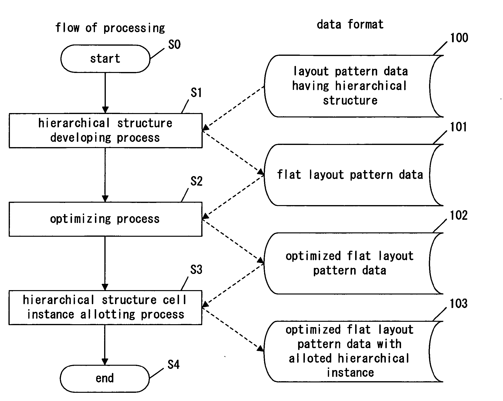
[0051]FIG. 1 is a flow chart of cell instance generation in Embodiment 1 of the present invention. Referring to the figure, the cell instance generating method of the present embodiment is explained in the following.
[0052] The left side of FIG. 1 shows the flow of the processing, and the right side of the figure shows the data formats of the layout pattern data that are inputted and outputted in each processing state.
[0053] According to FIG. 1, the outline of the cell instance generating method of the present embodiment is explained first.
[0054] When the processing starts at Step S0, a hierarchical structure developing process is performed to layout pattern data 100 at Step S1, and flat layout pattern data 101 is generated.
[0055] At Step S2, an optimizing process is performed to the flat layout pattern data 101, and optimized flat layout pattern data 102 is generated. By the process, a cell or more cells are newly inserted, in addition to the existing cells. The number of the ne...
embodiment 2
[0144]FIG. 7 is a partial exemplified schematic diagram illustrating optimized flat layout pattern data (in an intermediate state) with allotted hierarchical structure cell instance in Embodiment 2 of the present invention.
[0145] In the partial exemplified schematic diagram illustrating the flat layout pattern data shown in FIG. 7, the following instances are allotted to the existing cells, by the optimizing process and the hierarchical structure cell instance allotting process:
[0146] an instance “Chip / E / reg1” to a flip-flop 301;
[0147] an instance “Chip / F / reg1” to a flip-flop 302;
[0148] an instance “Chip / F / reg2” to a flip-flop 303;
[0149] an instance “Chip / G / reg1” to a flip-flop 305; and
[0150] an instance “Chip / F / and1” to an AND circuit 304.
[0151] In the partial exemplified schematic diagram illustrating the flat layout pattern data shown in FIG. 7, a buffer 306 is newly inserted by the optimizing process. The output port of the buffer 306 is connected to the flip-flop 302 via...
embodiment 3
[0173]FIG. 9 is a partial exemplified schematic diagram illustrating optimized flat layout pattern data (in an intermediate state) with allotted hierarchical structure cell instance in Embodiment 3 of the present invention.
[0174] In the partial exemplified schematic diagram illustrating the flat layout pattern data shown in FIG. 9, the following instances are allotted to the existing cells, after the optimizing process and the hierarchical structure cell instance allotting process:
[0175] an instance “Chip / H / reg1” to a flip-flop 401; and
[0176] an instance “Chip / J / reg1” to a flip-flop 402.
[0177] In the partial exemplified schematic diagram illustrating the flat layout pattern data shown in FIG. 9, buffers 403, 404, 405, and 406, connected each other in chain, are newly inserted for the timing adjustment.
[0178] The following explains how the cell instance generating method of the present embodiment is applied to generate instances for the new inserted buffers 403, 404, 405, and 40...
PUM
 Abstract
Description
Claims
Application Information
 - R&D Engineer
- R&D Manager
- IP Professional
- Industry Leading Data Capabilities
- Powerful AI technology
- Patent DNA Extraction
Browse by: Latest US Patents, China's latest patents, Technical Efficacy Thesaurus, Application Domain, Technology Topic, Popular Technical Reports.
© 2024 PatSnap. All rights reserved.Legal|Privacy policy|Modern Slavery Act Transparency Statement|Sitemap|About US| Contact US: help@patsnap.com