With the advent and advancement of weapon systems, for instance tactical weapons, the functionality of the “weapon” has become quite diverse, a challenge being to maintain an ease of use of the variety of features thereof, and avoidance of a cumbersome, inflexible and heavy
weapon system.
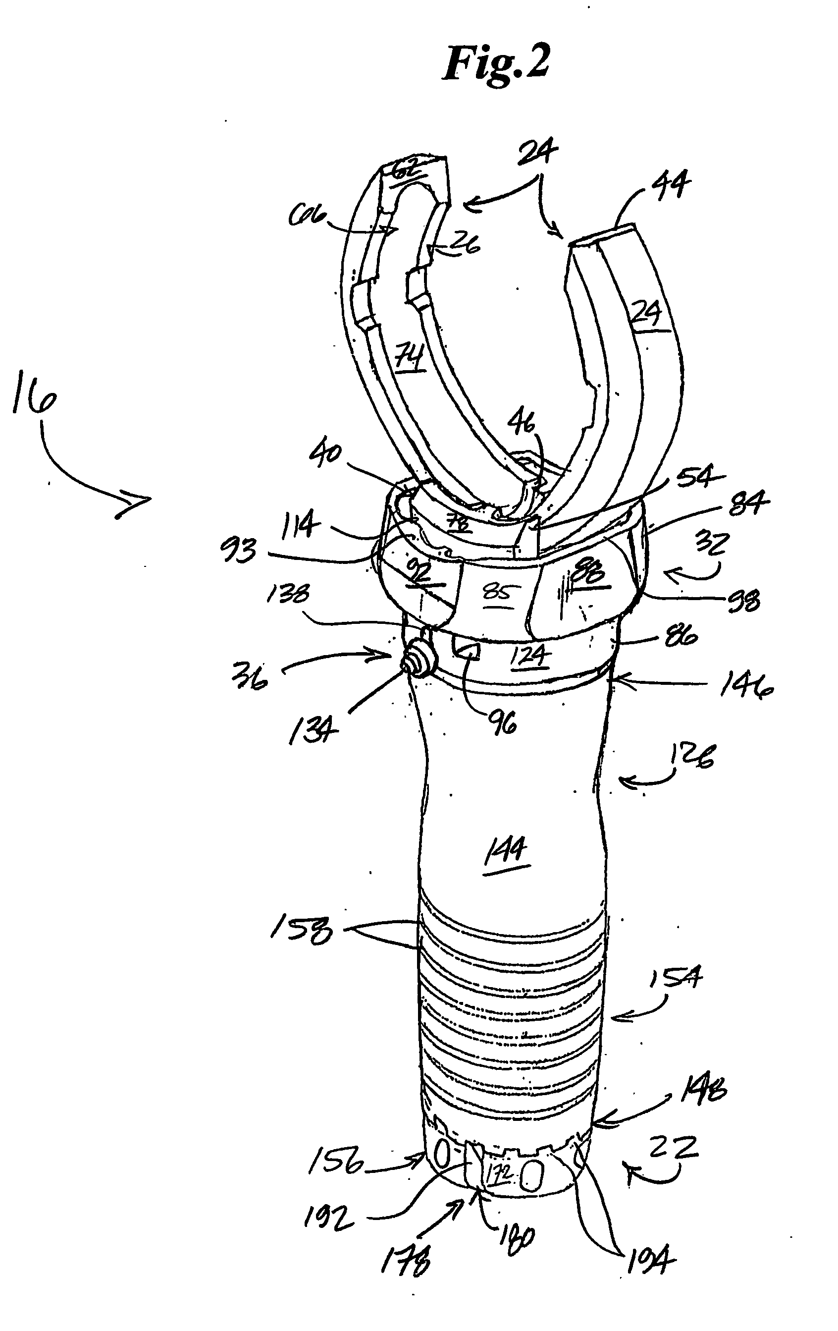
Although forward pistol grips are known and commercially available for integration with a forend assembly of a weapon, more particularly a rail or rail
system, the variety of forend configurations available for a weapon have precluded a more versatile, “one size fits all” solution for forwardly supporting a
weapon system in its variety of configurations.
While the above described attachment method of the launcher to the host
rifle may be the most practical solution for the integration of these separate devices, it does not provide the user with the best solution for carrying or operating the
rifle or the launcher when the two devices are combined.
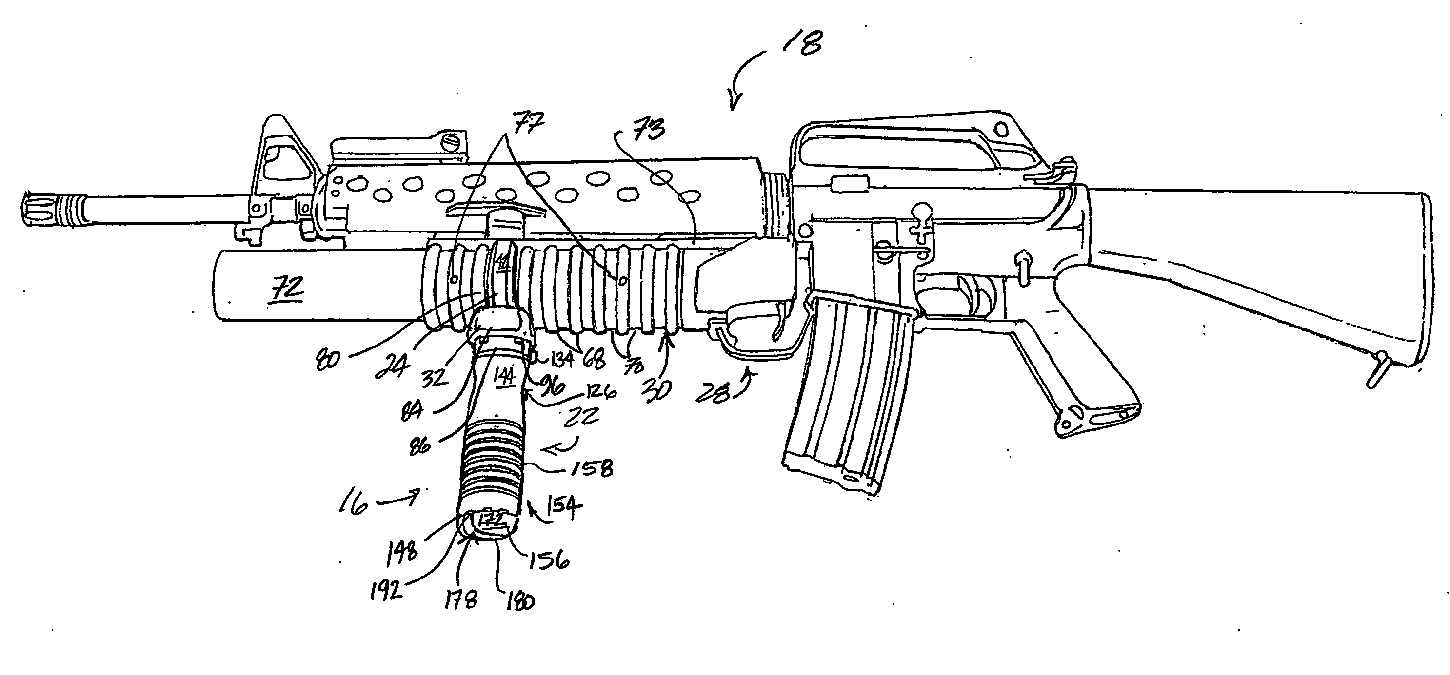
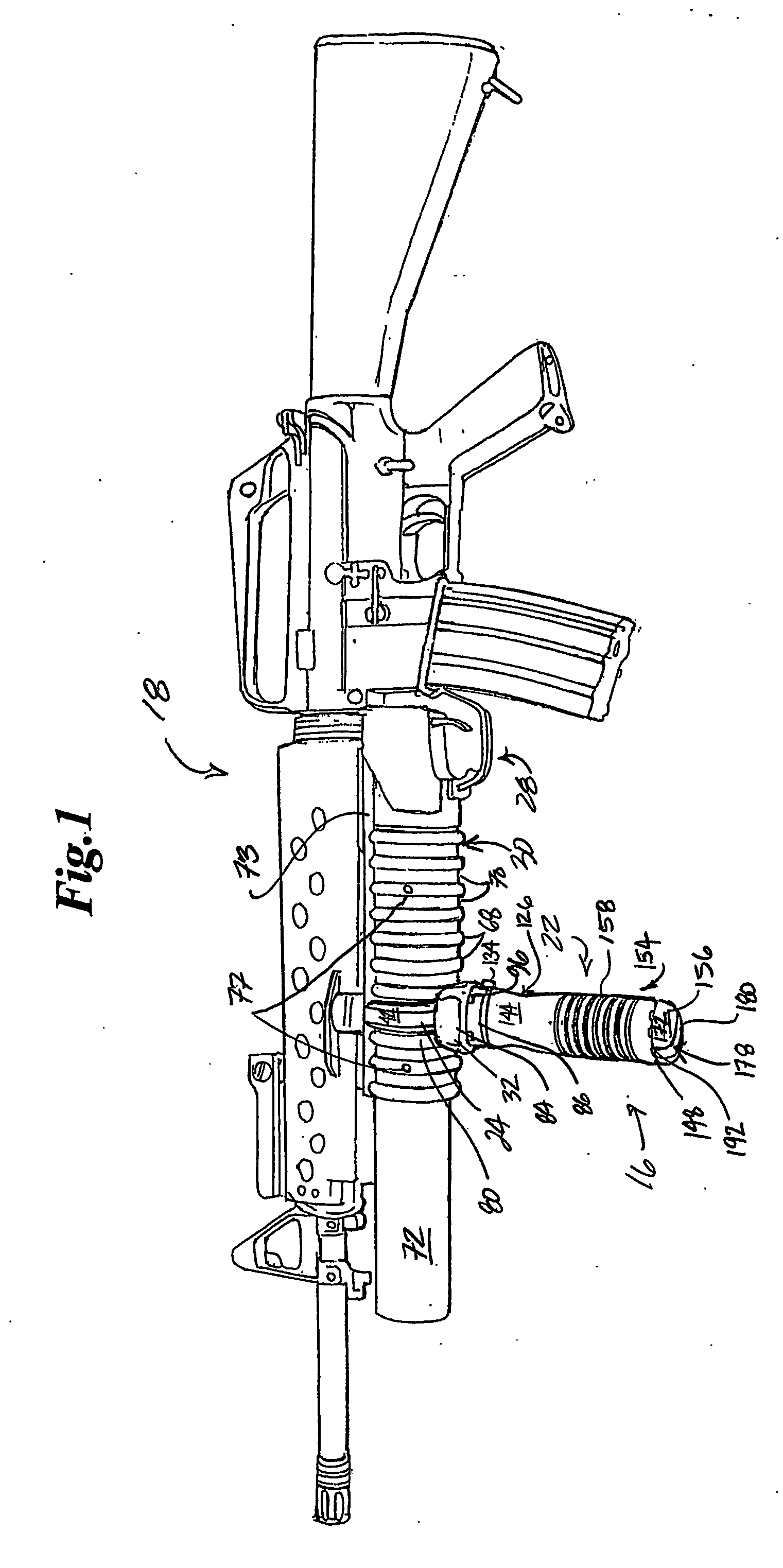
Because the
barrel is located below the launcher
receiver, the handguard does not and cannot fully encircle the
barrel, making it thereby impossible for the operator to wrap their hand around the
barrel to establish a strong grasp on the barrel.
This results in weak control of the weapon
system and increased operator fatigue due to the necessitated
hand position and orientation with respect to the weapon
system, more particularly, the launcher thereof.
With the knowledge that this
rifle / launcher combination is now front-heavy because of the shift in the rifle's center of gravity with the addition of the launcher, and that the handguard's
diameter and orientation are controlled by the functional characteristics of the launcher, both a user and non-user understands why this weapon
system combination, while highly desirable for its capabilities, is hard to control and is fatiguing to carry and operate, primarily because of the
hand position and orientation required.
There are many obstacles to developing a better way to grip the launcher.
Such structures may interfere with attachment solutions, and therefore require consideration.
As a matter of fact, the barrel handguard is adhesively adhered to the barrel because the barrel walls prohibit the use of fasteners.
Any solution requiring a
fastener which breaches the barrel wall is not possible.
Further still, the
thin wall of the barrel prevents any attachment solution which could distort the barrel by applying pressure unevenly, such a barrel being incapable of proper performance.
Any grip attachment solution which prevents or inhibits this barrel removal process is undesirable.
Furthermore, cleaning the barrel can be a messy affair using solvents to remove barrel reside and then repeatedly rinsing the barrel to remove the
solvent residue.
The barrel and handguard get contaminated on the outside during the process and must also be cleaned.
Any grip attachment solution that remains on the barrel during the cleaning process becomes another area to clean and is therefore undesirable.
Without removal it would be impossible to re-stake or change the barrel extension, repair or replace the
cartridge locator or the
cartridge locator spring.
Any grip attachment solution that remains in place in any of these areas would inhibit maintenance activities and is likewise undesirable.
Any grip attachment solution which is permanently affixed to the handguard would either inhibit or make this activity or exchange impossible.
The subject design has proved problematic, with the nub being susceptible to breakage and or deformation, and requiring further operator attention to appropriately position the grip upon the rail such that the nub will in fact fall into one of the many locating slots.
A further drawback of presently known rail
mount grips is the requirement that they be slid on, more particularly, they be slid onto the rail of the RAS from the weapon front (i.e., the
muzzle end) toward the weapon back (i.e. the butt stock end).
Known grips cannot be slid onto the rear end of the rail because there is not enough clearance between the rail end and rifle
receiver to allow access for alignment of the
flange with the rail.
Should a user wish to remove the grip from the weapon, or move it to a different rail to improve handling, a lot of
busy time is had configuring or reconfiguring the weapon.

