Smoke vent light transmitting roofing panel

Inactive Publication Date: 2006-08-31
LTP TECH
View PDF22 Cites 28 Cited by
  • Summary
  • Abstract
  • Description
  • Claims
  • Application Information

AI Technical Summary

Benefits of technology

[0016] It is a further object of this invention to provide a light transmitting panel which is inexpensive and may be constructed off site.
[0017] It is a still further o

Problems solved by technology

Unfortunately, skylights can be expensive and create water leakage.
One of the causes of water leakage is due to the restricted flow path of water between the domed skylight and the standing seam, whereby the water level rises such as to penetrate the roof at the panel junctions.
Additional problems arise with domed skylights when freezing temperatures are encountered.
Ice and/or snow may collect between the skylight and the dome, and as the ice melts it is blocked by ice dams resulting in the level of water rising and penetrating the panel seam.
However, curbs are expensive to construct and to install.
If not installed correctly leaks will develop around the curb and roof junction resulting in expensive repair.
Additionally, installing curbed skylights requires cutting a hole in the existing roof which is performed at the job site increasing the cost of the skylight.
However, the prior art skylights typically utilize flashing, mechanical fasteners, and or sealing rin

Method used


Image

  • Smoke vent light transmitting roofing panel
  • Smoke vent light transmitting roofing panel
  • Smoke vent light transmitting roofing panel

Examples


example

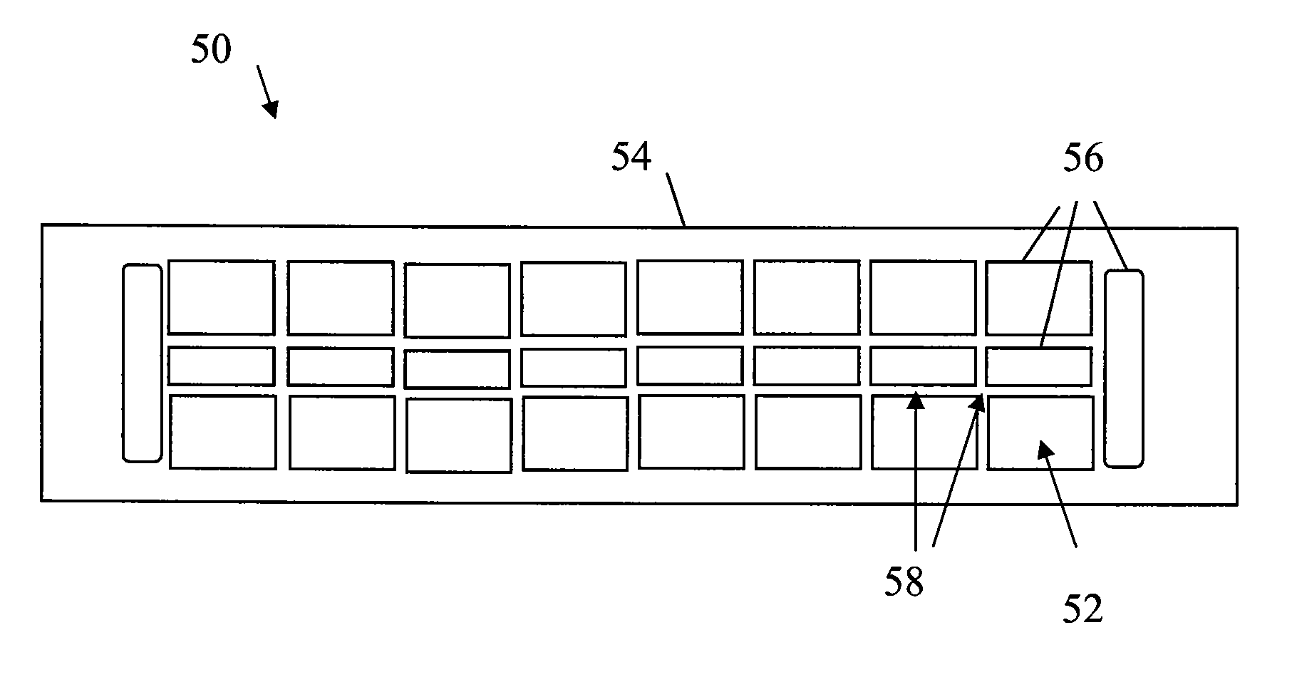
[0072] A light transmitting panel assembly according to the present invention was constructed for testing under UL 90 test requirements. A five (5) panel assembly was created wherein one of the panels included a light transmitting panel. The panels were nominally ten feet (10′) in length and two feet (2′) wide. The panel which comprised the light transmitting panel assembly included a metal panel including one cut-out nominally 17″×53″ and two cut-outs that nominally 17″×24″. A translucent fiberglass panel nominally 8 oz. / ft2 (˜0.045″ thick) was overlaid onto the metal panel so as to cover the cut-outs. A SIKA 252 adhesive was used as the linear coefficient buffer and was disposed between the metal panel and translucent fiberglass panel to a thickness of 2.5 mil. A neutral cure silicone (Silpruf manufactured by Bayer Corporation) was used as an addition adhesive / buffer on the light transmitting panel edges as a secondary seal and to prevent the infusion of air or water under the pan...


PUM


Abstract

A light transmitting panel capable of acting as a smoke vent and of the type for connecting within a metal roofing system is provided. The light transmitting panel includes a translucent panel that melts away rapidly under high temperature, a metal panel and a linear coefficient buffer therebetween to allow the respective panels to expand and contract with respect to the other without loss of containment or seal.

Description

CROSS-REFERENCE TO RELATED APPLICATIONS [0001] This application is a continuation-in-part of U.S. application Ser. No. 10 / 919,885, now U.S. Pat. No. ______, which is a continuation of U.S. application Ser. No. 09 / 860,156, filed May 17, 2001, now U.S. Pat. No. 6,775,951, which is a continuation-in-part of U.S. application Ser. No. 09 / 493,381, filed Jan. 28, 2000, now abandoned, each of these applications are hereby incorporated by reference herein, in their entirety.STATEMENTS REGARDING FEDERALLY SPONSORED RESEARCH OR DEVELOPMENT [0002] Not applicable. REFERENCE TO A MICROFICHE APPENDIX [0003] Not applicable. BACKGROUND OF THE INVENTION [0004] 1. Field of the Invention [0005] The present invention relates to smoke venting system for roofs, and more particularly, to a light transmitting panel that operates as a smoke vent within a metal roofing system. [0006] 2. Description of the Related Art [0007] For many years commercial buildings have utilized sheet metal roofs. Recently it has b...

Claims


Application Information

Patent Timeline
IPC IPC(8): E04D1/00
CPCE04D3/28E04D3/34E04D3/362E04D3/366E04D13/03F24F2011/0097Y10S52/17F24F11/34
Inventor GUMPERT, JOHN LARRY
Owner LTP TECH
Why Eureka
Try Eureka