Heat conductor with detection element and testing method thereof

Inactive Publication Date: 2006-08-31
FORCECON TECH CO LTD
View PDF2 Cites 0 Cited by
  • Summary
  • Abstract
  • Description
  • Claims
  • Application Information

AI Technical Summary

Benefits of technology

[0008] Based on this innovative design that heat conductor of the present invention is detected by an injecting micro detection element, it is possible to improve a time-consuming and slow testing process of testing one side's heat conduction via heating of the other side. In the present invention, only

Problems solved by technology

However, defective products shall be screened via a testing method since the vacuum state of finished products cannot be identified apparently after sealing of opening.
In the presence of abnormally slow speed or excessive temperature difference for both sides, they are proved non-conforming products below a vacuum state.
Based on practical experience of testing methods for the conventional heat conduc

Method used


Image

  • Heat conductor with detection element and testing method thereof
  • Heat conductor with detection element and testing method thereof
  • Heat conductor with detection element and testing method thereof

Examples


Embodiment Construction

[0014] The features and the advantages of the present invention will be more readily understood upon a thoughtful deliberation of the following detailed description of a preferred embodiment of the present invention with reference to the accompanying drawings.

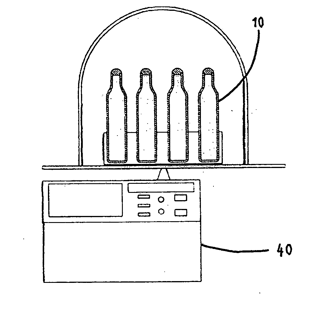
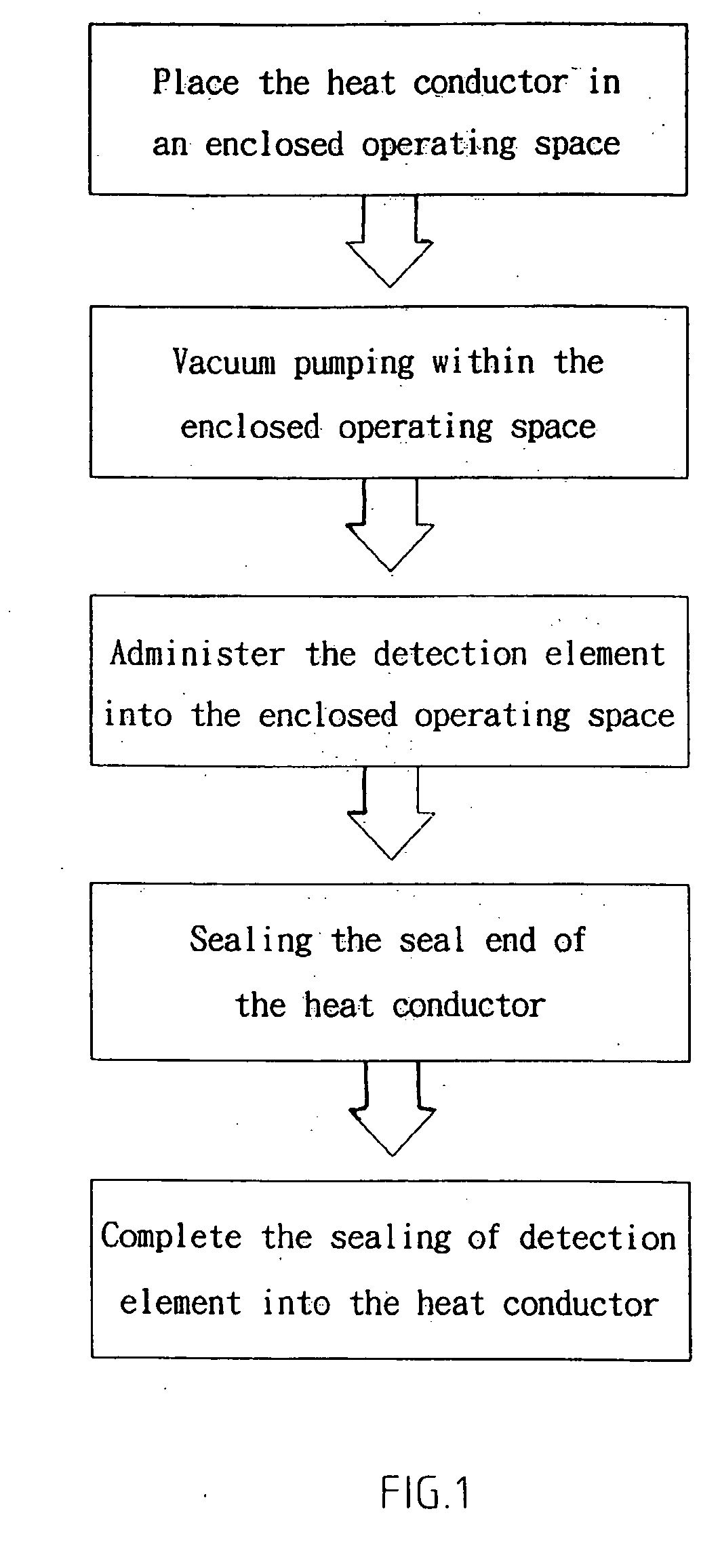
[0015] As shown in FIGS. 1-4, the testing method of a heat conductor with detection elements embodied in the present invention comprises:

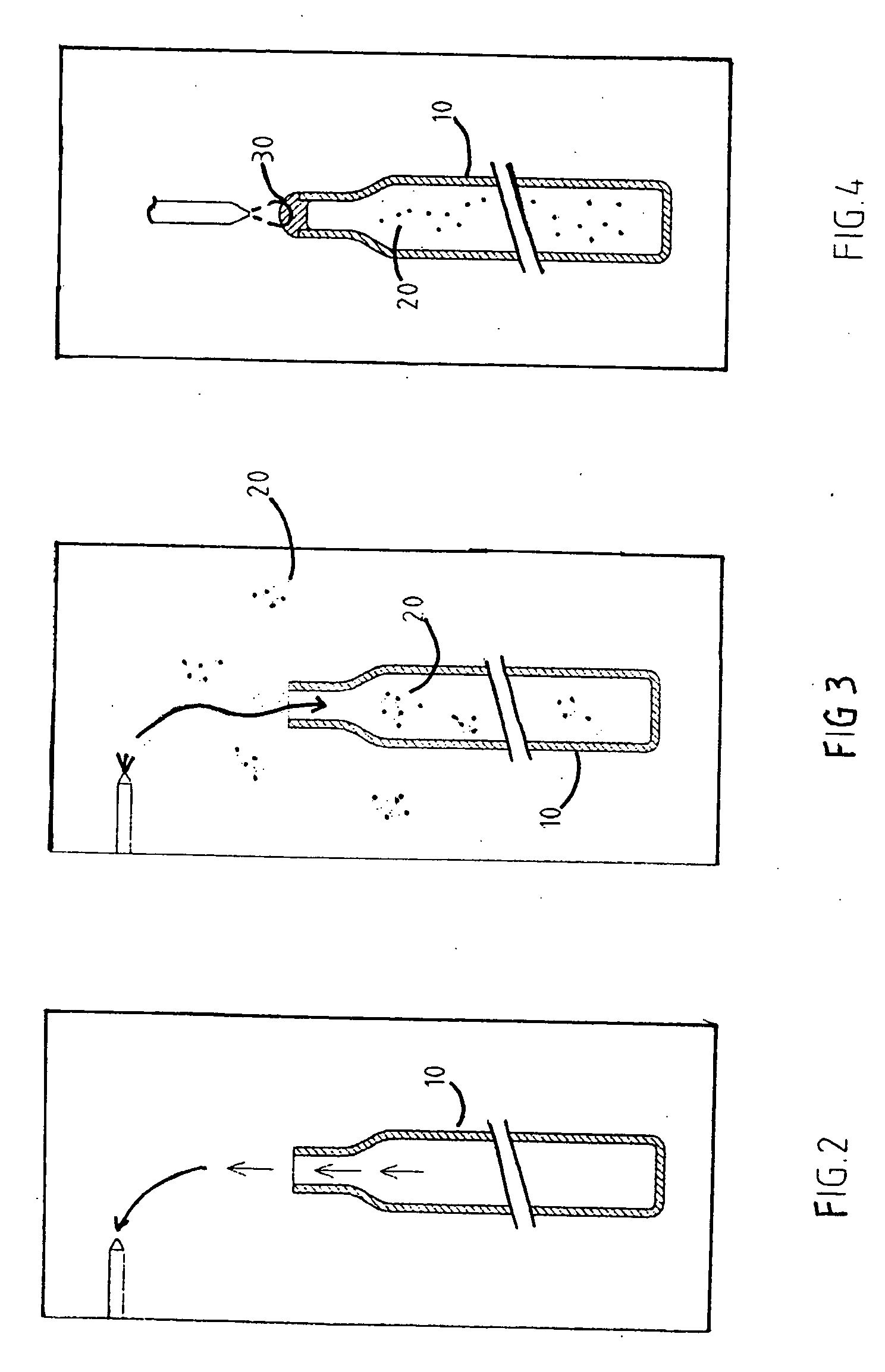
[0016] a. As shown in FIG. 2, vacuum pumping is performed within the heat conductor 10;

[0017] b. As shown in FIG. 3, micro detection element 20 is injected into heat conductor 10 after completion of vacuum pumping of heat conductor. The micro detection element generally refers to inert gases of lighter atomic weight, such as helium and argon, etc, which will be discharged if there is still any gap after sealing of heat conductor;

[0018] c. As shown in FIG. 4, the heat conductor 10 is sealed by soldering flux 30 or pressing methods;

[0019] d. As shown in FIG. 5, a special detector 40 for afo...


PUM


Abstract

The heat conductor with a micro detection element and a testing method thereof. The method includes injecting the micro detection element into the heat conductor after completion of vacuum pumping for the heat conductor. The micro detection element generally refers to inert gases of lighter atomic weight, such as helium and argon, etc. Next, the heat conductor is sealed. Secondly, a detector is used to detect if there is any leakage of micro detection element from exterior of heat conductor. The invention makes possible speeding up the test process and quickly identifying the vacuum state of heat conductor for a higher availability.

Description

RELATED U.S. APPLICATIONS [0001] Not applicable. STATEMENT REGARDING FEDERALLY SPONSORED RESEARCH OR DEVELOPMENT [0002] Not applicable. REFERENCE TO MICROFICHE APPENDIX [0003] Not applicable. FIELD OF THE INVENTION [0004] The present invention relates generally to the testing method and construction of a heat conductor, and more particularly to an innovative design that a heat conductor includes a micro detection element for rapid detection of the vacuum state. BACKGROUND OF THE INVENTION [0005] To ensure a better heat conduction effect, a heat conductor is generally fitted with an opening at one side for vacuum pumping. After that, it is required to keep the vacuum constant by sealing this preset opening. However, defective products shall be screened via a testing method since the vacuum state of finished products cannot be identified apparently after sealing of opening. According to existing testing methods, the finished heat conductor shall be continuously warmed up after vacuum ...

Claims


Application Information

Patent Timeline
IPC IPC(8): G01M3/04
CPCG01M3/226
Inventor SHIH, MING-CYUANHE, SIN-WEICHANG, JHONG-YAN
Owner FORCECON TECH CO LTD
Why Eureka
Try Eureka