Heat exchanger having an improved baffle

a technology of heat exchanger and baffle, which is applied in the field of multifluid heat exchanger, can solve the problems of reducing performance, reducing the function or efficiency of one or more heat exchanger tubes, and reducing so as to facilitate leak detection, reduce the overall width of the baffle, and shorten the tube spacing

Inactive Publication Date: 2005-09-13
VALEO INC
View PDF15 Cites 14 Cited by
  • Summary
  • Abstract
  • Description
  • Claims
  • Application Information

AI Technical Summary

Benefits of technology

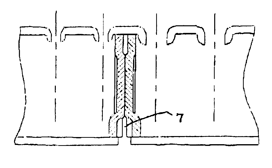
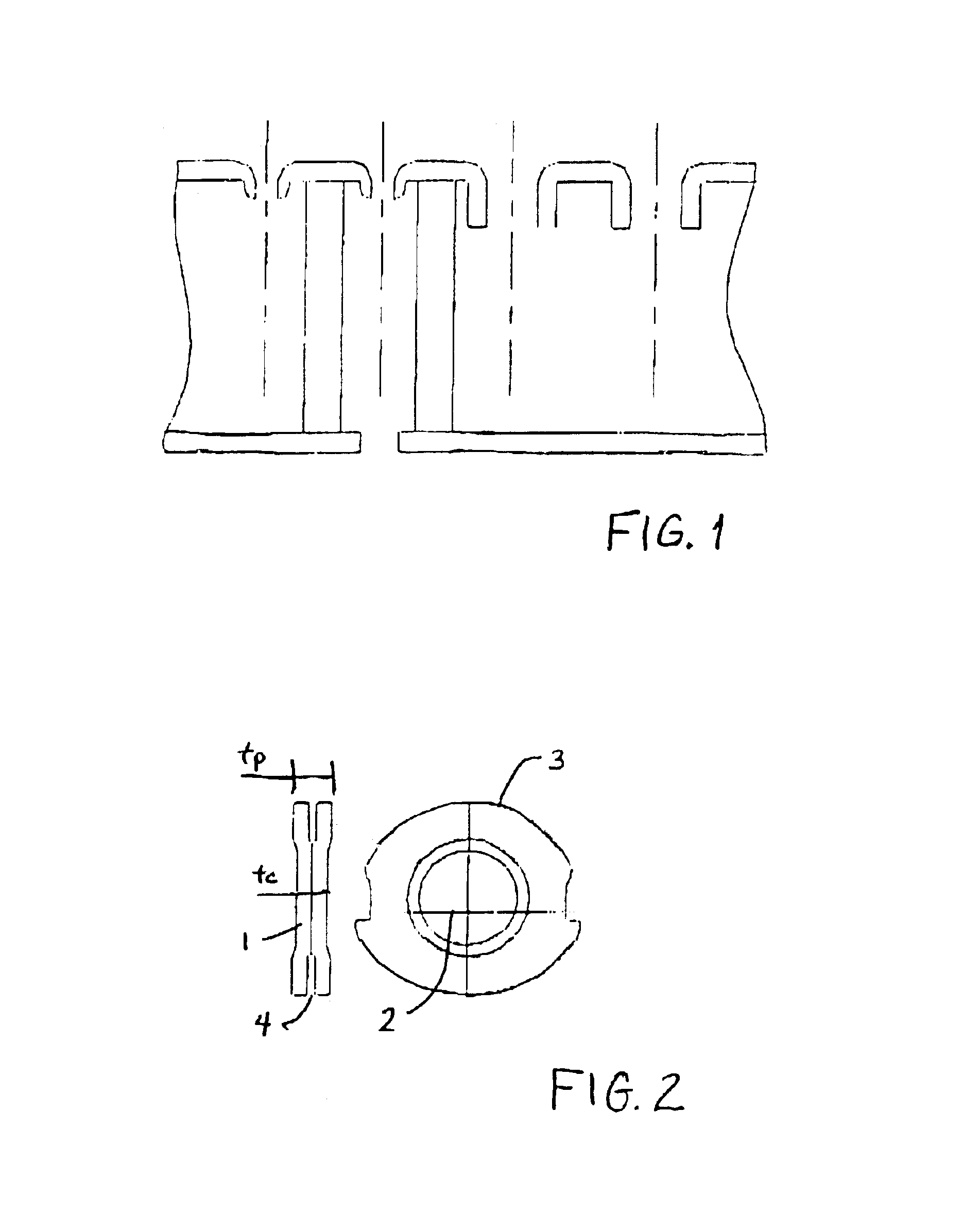
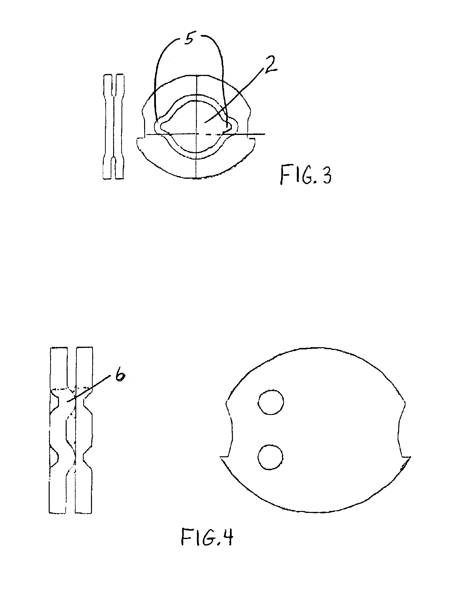
[0006]In a particular embodiment of the invention, a “hole” or “weep hole” may be placed on the cover surface between double baffles, to provide a communication towards the exterior. In an even more preferred embodiment, the entry passage is placed on the cover surface so as to enable entry of (fluid) materials) such as flux, to prepare any wetted surfaces for brazing or the like. An additional preferred feature and advantage of such an embodiment is that said entry passage may also provide a means to facilitate leak detection. In preferred embodiments, the double baffle has an outer perimeter edge separated by a short distance to provide a relief channel at the sealing edge. Even more preferred is a sealing edge which is not ‘rolled’ or flanged, thus reducing the overall width of the baffle between the tubes for shorter tube spacing. In a particularly preferred embodiment, the double baffle is of a reduced thickness being assembled back to back with a common center contact portion area, which leads to the central portion much increased and may preferentially be one and one half time, double or more, than the thickness to resist higher pressures. The sealing perimeter outward variance of preferred embodiments also provide greater axial stability of the baffle during assembly.

Problems solved by technology

However, until the present invention, baffle designs have often resulted in space problems, and the like, contributing to the loss of function or efficiency of one or more of the heat exchanger tubes.
In particular, certain heat exchanger assemblies may have space requirements that extend to at least one core tube end in the tank.
In such assemblies, space restrictions have led to “rolling” of baffle perimeter walls or “flanges” that increase bonding against the tank perimeter and take up additional space that eventually restricts performance due to the fact that tube center to center spaces can not be optimized.

Method used


Image

  • Heat exchanger having an improved baffle
  • Heat exchanger having an improved baffle
  • Heat exchanger having an improved baffle

Examples


Embodiment Construction

[0013]Generally, the present invention relates to a heat exchanger and to a method of forming the heat exchanger. The heat exchanger may be a single fluid or multi-fluid (e.g., 2, 3 or 4 fluid) heat exchanger. The heat exchanger may also be a single pass or multi-pass heat exchanger. Although the heat exchanger according to the present invention may be used for a variety of articles of manufacture (e.g., air conditioners, refrigerators or the like), the heat exchanger has been found particularly advantageous for use in automotive vehicles. For example, the heat exchanger may be used for heat transfer of one or more various fluids within a vehicle such as air, oil, transmission oil, power steering oil, radiator fluid, refrigerant, combinations thereof or the like. For example, in a highly preferred embodiment of the present invention there is contemplated a multi-fluid heat exchanger that includes a condenser in combination with an oil cooler selected from the group consisting of a p...


PUM


Abstract

The present invention is directed to a heat exchanger for an automotive vehicle. The heat exchanger includes a first end tank divided into a first portion and a second portion by a baffle, the first end tank including a through-hole.
The baffle system includes a baffle or baffles with a central portion and at least one flanged peripheral portion, the flanged peripheral portion having a peripheral channel. Additionally, the baffle preferably is disposed within the end tank so that the peripheral channel is substantially juxtaposed with the through-hole in the end tank for providing a visual leak indicator.

Description

FIELD OF THE INVENTION[0001]The present invention relates generally to a heat exchanger and more particularly a multi-fluid heat exchanger, employing an improved baffle.BACKGROUND OF THE INVENTION[0002]In the automotive industry, in particular, it has become increasingly necessary to combine multiple functions in a single heat exchanger assembly. The need to reduce the number of overall components and to optimize assembly efficiency has driven the need for improved heat exchanger devices that combine increasingly efficient designs and multiple functions in packaging heretofore attainable using plural separate components or devices having inefficient designs. More specifically, there has been a growing need for an improved heat exchanger device, particularly for under the hood automotive vehicle applications, which combines multiple functions in a single assembly that is efficient to make and operate and that occupies substantially the same or less space than existing heat exchanger ...

Claims


Application Information

Patent Timeline
Patent Type & Authority Patents(United States)
IPC IPC(8): F28F9/02F28D1/04
CPCF28D1/0408F28F9/0212
Inventor BONNET, PASCAL
Owner VALEO INC
Why Eureka
Try Eureka